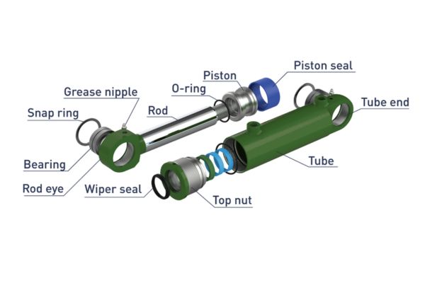
What Is Hydraulic Cylinder and How It Works in Applications
What is a hydraulic cylinder but the literal muscle of your heavy machinery, converting fluid energy into powerful linear force? When your equipment faces extreme workloads, this components ensures smooth, precise motion control.
What Is a Hydraulic Cylinder in Modern Industrial Systems?
A hydraulic cylinder is a linear actuator that converts hydraulic fluid energy into powerful mechanical force and straight-line motion. It operates as the core muscle in high-pressure systems, handling loads that mechanical or electrical drives cannot manage.
Have you ever wondered how heavy equipment achieves such immense force? The secret lies in fluid power distribution.
Understanding the Fluid Power Conversion
To grasp this technology, you must examine how fluid pressure translates directly into mechanical displacement. High-pressure oil enters the chamber, pushing the internal piston with immense energy.
The fluid cannot compress, meaning every ounce of pump energy transfers straight to your machine’s working arm.
- Unyielding linear force output for heavy lifting
- Precise stroke control under fluctuating loads
- Complete containment of high-pressure hydraulic fluids
This mechanical process guarantees that your machinery reacts instantly to operator commands under any load condition.
Critical Components That Prevent System Failure
Every heavy-duty actuator relies on a network of precision-engineered internal parts to maintain structural integrity. The cylinder barrel, piston rod, and sealing elements must endure constant friction and extreme thermal changes.
- Heavy-wall steel tubing designed to withstand internal pressure spikes
- Induction-hardened, chrome-plated rods that resist pitting and environmental corrosion
- Advanced polyurethane seal configurations that stop external oil leaks completely
Investing in high-grade component materials saves you from unexpected rod bending and early seal degradation during peak operation hours.
| Component Name | Primary Function | Common Material |
| Cylinder Barrel | Contains high internal fluid pressure | Honed Carbon Steel Tubing |
| Piston Rod | Transmits linear force to the load | Chrome-Plated Steel |
| Sealing System | Prevents internal and external fluid bypass | Polyurethane / Nitrile Rubber |
How Does Fluid Pressure Generate Immense Linear Force?
A hydraulic cylinder generates linear force by applying pressurized fluid against the surface area of an internal piston. This mechanical process follows Pascal’s law, which states that pressure applied to a confined fluid transmits undiluted throughout the medium.
The Role of Pascal’s Law in Heavy Machinery
The fluid power system amplifies input force by shifting oil from a small pump area to a larger cylinder volume. This hydraulic advantage allows a compact power unit to move multi-ton industrial loads easily.
The pump forces oil into the cylinder, and because the fluid cannot compress, it exerts equal force against every square inch of the internal piston.
- Continuous force amplification without mechanical gear wear
- Smooth, vibration-free movement across the entire stroke length
- Instant acceleration and deceleration control via directional valves
Mastering this pressure distribution helps you troubleshoot sudden drops in machine lifting capacity.
Fluid Displacement and Stroke Speed Dynamics
The velocity of your actuator depends directly on the flow rate of the oil entering the chamber. Increasing the gallons per minute accelerates the piston rod, while expanding the piston diameter increases total lifting force.
You cannot increase speed and force simultaneously without increasing the total input horsepower of your hydraulic pump.
- Flow rate determines total rod extension speed
- Piston surface area dictates ultimate load capacity
- Return-line restrictions can cause unwanted backpressure issues
Balanging your system’s flow rate ensures your machinery operates at peak efficiency without overheating the fluid.
| Parameter Type | Impact on Performance | System Variable |
| High Flow Rate | Increases piston rod extension speed | Pump GPM Output |
| Large Piston Area | Multiplies total output lifting force | Cylinder Bore Diameter |
| Fluid Viscosity | Affects system friction and pressure drops | Oil Temperature |
Why Are Single-Acting Cylinders Used for One-Directional Loads?
Single-acting cylinders use pressurized fluid to extend the rod in one direction, relying on gravity or an internal spring to retract it. They are common in simple lifting applications where the load itself provides the necessary return force.

The Mechanics of Spring and Gravity Returns
These actuators feature a single fluid port on one end of the cylinder housing. Pressurized oil enters this port to push the piston forward, compressing an internal spring or lifting a heavy mechanical weight.
Once the directional control valve shifts to the neutral position, the heavy load or spring pushes the oil back through the single line.
- Simplified single-line plumbing reduces overall installation costs
- Fewer internal seals mean less friction and lower maintenance needs
- Dependable gravity return reduces reliance on complex control valves
This straightforward mechanical design makes single-acting units perfect for simple industrial dump bodies and mobile scissor lifts.
Common Application Environments for Single-Acting Units
You will frequently find these components in truck lift gates, material handling stackers, and heavy-duty workshop presses. They excel in environments where force is only required during the upward or outward movement phase.
Because these units require less hosing, they are ideal for compact mobile machinery frames.
- Heavy-duty industrial hydraulic jacks for structural lifting
- Warehouse dock levelers requiring simple gravity descent
- Automated assembly line clamping fixtures with spring returns
Selecting single-acting models for unidirectional tasks reduces system complexity and saves valuable build budget.
| Feature Category | Single-Acting Behavior | Operational Benefit |
| Fluid Ports | One single pressure port | Reduced hosing costs |
| Return Mechanism | Gravity or mechanical spring | Zero fluid energy used for return |
| Installation Space | Compact housing design | Fits into tight machine frames |
Evaluating these simple design aspects helps you eliminate unnecessary valving on basic material handling machinery.
When Should You Specify Double-Acting Hydraulic Cylinders?
Double-acting hydraulic cylinders utilize pressurized fluid to drive the piston rod in both extension and retraction directions. This design provides precise control and consistent force throughout both phases of operation, making it necessary for complex movements.
Dual-Port Fluid Distribution Systems
These units feature two separate fluid ports located at the base end and the rod end of the cylinder barrel. The directional control valve switches pump flow between these ports to alternate movement directions.
Here is what happens when the control valve changes position. Pressurized oil enters the rod end while the base end opens to the return line, pulling the load back smoothly.
- Bi-directional force generation for versatile machine motion
- Controlled deceleration on both ends of the stroke
- Complete operator control over pulling and pushing cycles
This dual-port design gives you the mechanical precision needed for complex multi-axis manufacturing automation.
Handling Tensile and Compressive Loads Alternately
Industrial applications like excavators, manufacturing presses, and steering systems demand equal control during extension and retraction. Double-acting actuators prevent uncontrolled drops or sudden shifting when loads change directions.
This happens because the internal rod occupies valuable surface area on the retraction side of the piston.
- High pulling force for heavy mechanical retraction tasks
- Balanced speed characteristics during automated cycling
- Integration with counter-balance valves for load holding
Understanding this force difference prevents structural failure when your machine switches from a push to a pull cycle.
| Stroke Direction | Effective Piston Area | Relative Force Output |
| Extension (Push) | Full Bore Surface Area | Maximum Force Potential |
| Retraction (Pull) | Bore Area Minus Rod Area | Reduced Force / Higher Speed |
| Neutral Holding | Blocked Fluid in Both Ports | Locked Mechanical Position |
What Causes Hydraulic Cylinder Seal Failure and Internal Leaks?
Seal failure occurs when extreme heat, fluid contamination, or pressure spikes damage the polyurethane or rubber sealing elements inside the cylinder. This damage allows pressurized oil to bypass the piston or leak past the rod wiper, causing system pressure loss.
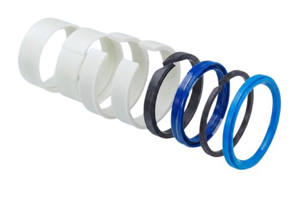
The Impact of Fluid Contamination on Soft Seals
Microscopic metal shavings, dirt, and water acting as abrasive compounds inside the oil stream quickly destroy polished surfaces. As the piston cycles, these contaminants cut deep grooves into the soft sealing lips.
You have to realize that clean oil is the lifeblood of your entire fluid power system. Once a piece of grit settles into the seal groove, it acts like sandpaper against the moving rod.
- Microscopic tracking paths allow high-pressure fluid bypass
- Rapid wear of wear bands causes internal metal-to-metal contact
- Torn rod wipers allow environmental dust into the barrel
Maintaining strict fluid filtration standards protects your internal seals from premature degradation and extends component lifespans.
Thermal Degradation and Pressure Spikes
Operating a system beyond its rated thermal limits cooks the internal seals, making them brittle and prone to cracking. Sudden pressure spikes from dropping heavy loads can fracture backup rings and blow out sealing lips.
Overheated polyurethane loses its elasticity, hardens like plastic, and fails to maintain contact with the moving rod surface.
- Hardened, brittle seal lips that fracture under normal pressure
- Blown-out backup rings caused by extreme pressure spikes
- Accelerated chemical breakdown of the hydraulic oil medium
Installing robust oil cooling equipment keeps your fluid temperatures stable and protects your internal components from thermal hardening.
| Failure Symptom | Root Cause | Preventive Action |
| External Oil Drpping | Damaged or worn rod seal | Replace seal and check rod finish |
| Cylinder Drift | Internal piston seal bypass | Flush system and install new seals |
| Brittle, Cracked Seals | High operating fluid heat | Clean heat exchangers and check oil |
How Do Tie-Rod and Welded Cylinders Differ in Construction?
Tie-rod cylinders use high-strength threaded steel rods outside the barrel to hold the end caps securely against the tube. Welded cylinders feature heavy-duty end caps welded directly to the barrel, creating a compact and rigid structure.
Tie-Rod Designs for Industrial Plant Equipment
Tie-rod models dominate the industrial factory floor due to their standardized NFPA mounting patterns and ease of repair. You can completely disassemble these units using standard hand tools to replace worn internal seals quickly.
This is why plant managers prefer them for indoor manufacturing lines. If an internal seal wears out, you simply unbolt the tie-rods, service the components, and reassemble the unit on-site.
- Standardized dimensions make sourcing replacement units fast and simple
- Easy disassembly reduces total machine maintenance down-time
- Bolted construction allows custom end-cap modifications
While highly practical for indoor factory use, the external rods can collect dirt and debris in dirty outdoor applications.
Welded Bodies for Rugged Mobile Equipment
Welded actuators are the preferred choice for construction machinery, mining equipment, and agricultural vehicles. Their smooth, round exterior prevents dirt accumulation and allows them to fit into tight structural spaces.
The welded design handles higher pressures and eliminates the risk of tie-rod stretching under sudden mechanical shock.
- Compact outer dimensions fit narrow machinery frames perfectly
- Welded end caps prevent barrel expansion under extreme pressure
- Smooth exterior resists dirt buildup in harsh outdoor environments
Specifying welded units for mobile applications prevents structural deflection when your machinery hits heavy rocks or hard ground.
| Construction Attribute | Tie-Rod Cylinder Style | Welded Cylinder Style |
| Pressure Rating | Medium to High (NFPA Standards) | Ultra-High (Heavy Mobile Duty) |
| Maintenance Method | Bolted assembly / Easy field repair | Threaded gland or welded / Special tools |
| Outer Profile | Square end caps with exterior rods | Sleek, round profile with minimal clearance |
Which Mounting Configuration Fits Your Machine Geometry Best?
Mounting configurations determine how the cylinder attaches to your machine frame and transfers linear force to the load. Choosing between pivot mounts or fixed mounts depends on whether your mechanism travels in a straight line or sweeps through an arc.
Pivot Mounts for Angular Machinery Motion
Clevis, pin, and spherical bearing mounts allow the cylinder body to swing freely as the rod extends and retracts. This movement is necessary for equipment like dump truck beds and excavator arms that change angles during operation.
Think about how an excavator arm moves through its lifting cycle. The cylinder must pivot continuously to prevent the chrome rod from bending against the stationary mounting bracket.
- Clevis mounts allow single-plane angular rotation
- Spherical bearings correct minor multi-axis alignment errors
- Trunnion mounts offer flexible pivot points along the barrel length
Using pivot mounts protects your internal wear bands from uneven friction when moving loads travel along non-linear paths.
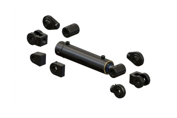
Fixed Mounts for Precise Straight-Line Thrust
Flange, foot, and extended tie-rod mounts lock the cylinder body flat against a stationary machine frame structure. These configurations are ideal for industrial manufacturing presses, stamping machines, and heavy-duty injection molding equipment.
You should choose a fixed flange mount when your application requires maximum rigidity. Bolt the front flange directly to your frame to ensure the linear thrust aligns perfectly with your machine guide rails.
- Front flange mounts handle high compressive pushing forces
- Rear flange configurations excel during high-tension pulling cycles
- Side foot mounts simplify alignment along flat machine platens
Securing your cylinder with rigid fixed mounts eliminates structural flexing and improves the accuracy of automated cutting operations.
| Mounting Category | Connection Style | Ideal Motion Path |
| Clevis / Pin | Pivot Mount | Curved arc / Angular movement |
| Front / Rear Flange | Fixed Mount | Strict straight-line mechanical thrust |
| Trunnion Mount | Mid-Body Pivot | Long strokes with changing angles |
How to Calculate Cylinder Force and Fluid Flow Requirements?
Calculating cylinder force requires multiplying the operational fluid pressure by the effective surface area of the internal piston face. Determining flow requirements requires multiplying that piston area by your desired cycle stroke speed.
Calculating Piston Area and Force Potential
To calculate force, square the radius of your cylinder bore, multiply by pi, and multiply that area by your system pressure. Remember to subtract the rod area when calculating your retraction or pulling force.
Here is the exact formula you need to use for your calculations. Force equals Pressure times Area, meaning a four-inch bore at three thousand PSI delivers over thirty-seven thousand pounds of push.
- Bore diameter determines total extension surface area
- Rod diameter reduces total retraction surface area
- Higher operating pressure increases force without changing cylinder size
Using these exact engineering calculations prevents you from purchasing underpowered actuators that stall out when lifting heavy loads.
Determining Flow Rates for Specific Cycle Speeds
To achieve a specific stroke speed, you must supply enough fluid volume to fill the cylinder barrel in a set time frame. Divide the total internal cylinder volume by your required stroke time to find the necessary pump flow rate.
You need to pay close attention to your hose sizes when designing this fluid system. Selecting small diameter hydraulic hose sizes causes high fluid friction and slows down your overall cycle speed.
- Volume equals internal bore area multiplied by stroke length
- Pump GPM dictates how fast that volume fills with oil
- Return lines must handle the displaced oil without causing backpressure
Sizing your pump and hosing correctly ensures your machinery runs at production speed without creating power-wasting heat.
| Metric Type | Calculation Formula | Practical Impact |
| Extension Force | Area of Bore* Fluid Pressure | Maximum load lifting capability |
| Retraction Force | (Bore Area-Rod Area) *Pressure | Maximum load pulling capability |
| Required Fluid Flow | Cylinder Volume / Target Time | Piston rod extension and cycle speed |
What Are the Best Practices for Hydraulic Cylinder Maintenance?
Best practices for maintenance include conducting regular oil contamination testing, checking rod surfaces for damage, and monitoring system temperatures. Catching minor seal weeping early prevents catastrophic hydraulic failure and avoids expensive unexpected production stops.
Routine Inspection Protocols for Service Crews
Your maintenance technicians should inspect the chrome plating on the piston rods for scratches, pits, or uneven wear marks during every shift change. Wipe down the external gland area to check for oil leaking past the main rod seal.
If you spot fine metallic dust near the wiper seal, stop the machine immediately to check for internal metal-to-metal rubbing.
- Check rod chrome plating for deep scratches or pitting
- Monitor rod seal area for continuous oil dripping
- Inspect mounting pins for lubrication levels and structural cracks
Catching these external warning signs early allows you to schedule seal replacements during planned plant maintenance windows.
Fluid Maintenance and Filtration System Audits
Keeping your oil clean is the most effective way to extend the operating life of your hydraulic cylinders and control valves. Replace your system filters regularly and sample the oil to check for microscopic particle contamination.
Never mix different oil types or pour fresh oil straight into your machine reservoir without filtering it first. New oil from a drum often contains particles that can score polished internal surfaces.
- Maintain an ISO 4406 fluid cleanliness level of 18/16/13 or better
- Check your return-line filter indicators during warm machine operation
- Monitor your system operating temperature to prevent oil thinning
Keeping your hydraulic fluid clean and cool protects your internal seals and maintains reliable system operating pressure.
| Inspection Task | Recommended Frequency | Targeted Component |
| Visual Leak Check | Daily / Every Shift Change | Main Rod Seal and Wiper |
| Oil Sampling | Quarterly / Every 500 Hours | System Fluid and Filters |
| Mount Lubrication | Weekly / Every 40 Hours | Clevis Pins and Bearings |
How to Troubleshoot a Drifting Hydraulic Cylinder Effectively?
To troubleshoot a drifting cylinder, you must determine if fluid is bypassing the internal piston seals or leaking through the external directional valve. Drift happens when a mechanical load slowly moves the piston rod while the control valve is in the neutral position.
Isolating the Cylinder from the Control Valve Circuit
To test the internal seals, extend the cylinder completely, turn off the power unit, and safely block the mechanical load. Disconnect the return line hose carefully at the rod end port and place it into a clean measuring container.
Now, apply system pressure to the opposite port and watch for oil draining out of the open rod end connection. If fluid flows continuously from this open port, your internal piston seals are worn and must be replaced immediately.
- Continuous oil flow indicates worn or torn piston seals
- Zero oil flow means the internal sealing system is working correctly
- A dry port points to a leaking external directional control valve
This simple test prevents you from wasting time replacing good seals when the real problem is a worn control valve spool.
Inspecting the Valve Spool and Holding Cartridges
If the cylinder passes the port isolation test, your drift issue is likely caused by oil slipping past a worn control valve spool. Inspect your counterbalance valves and pilot-operated check valves for dirt that might hold the internal sealing seats open.
You must clean these small valve cartridges carefully using compressed air and fresh solvent. A single tiny grain of sand inside a check valve seat can cause an entire multi-ton mechanical arm to drift downward dangerously.
- Inspect check valve sealing seats for debris or deep wear marks
- Check control valve spool clearances for excessive clearance wear
- Replace soft O-rings on external cartridge valve bodies
Cleaning your valve network and replacing worn cartridges restores full load-holding capabilities to your heavy machinery.
| Test Result | Indicated Root Cause | Required Corrective Action |
| Oil flows from open port | Worn or torn piston seals | Disassemble barrel and replace seals |
| Open port remains dry | Leaking control valve spool | Repair or replace directional control valve |
| Holding valve drips oil | Dirty or damaged check seat | Clean cartridge or replace holding valve |
Conclusion
Optimizing your fluid power systems requires a solid understanding of force calculations, structural construction styles, and proactive seal maintenance protocols. Selecting the ideal tie-rod or welded cylinder, matching it with the correct pivot or fixed mount, and maintaining clean fluid ensures your heavy machinery delivers maximum performance over a long operating life.
If your production lines are facing unexpected downtime or handling complex machinery upgrades, finding the right fluid power components is essential. Our engineering team specializes in sourcing high-pressure hydraulic cylinder tailored to your specific industrial applications.
Frequently Asked Questions
Can I replace a single-acting cylinder with a double-acting model on my machine?
Yes, you can install a double-acting model, but you must add a second hydraulic line and update your directional control valve to manage fluid flow in both directions. Without these secondary plumbing lines and proper valving, the new unit will not retract under power.
What’s the best way to stop a chrome piston rod from rusting in outdoor environments?
The most effective method is to store the machinery with the piston rods fully retracted so the chrome surface stays submerged in protective hydraulic oil. For exposed rods that must remain extended outdoors, apply a thick layer of specialized marine grease or premium corrosion-inhibiting spray to protect the chrome plating from moisture.
How do I know if my cylinder is drifting due to bad seals or a bad valve?
You can find out by extending the rod completely, safely blocking the load, and disconnecting the return line hose at the cylinder port. Apply pressure to the opposite side; if oil flows out of the open port, your internal piston seals are bypassing fluid and need replacement.
How often should I test the cleanliness of my hydraulic oil?
You should sample and test your fluid every three to six months, or every five hundred operating hours, depending on your environment. Dirty construction sites require more frequent testing than clean indoor manufacturing plants to prevent abrasive particles from destroying your soft seals.
Can I repair a scored cylinder barrel, or do I need to buy a complete replacement?
Minor surface scratches can often be removed using a flexible honing tool, but deep grooves require replacing the entire steel tube assembly. Operating a cylinder with a scored barrel will quickly cut your new piston seals, causing immediate internal fluid bypass and pressure loss.