How to Simplify Hydraulic Cylinder Work Principle for Beginners
A heavy industrial tractor loader stalls midway through a critical bulk silage loading cycle, its heavy bucket drifting downward despite your controls remaining locked in the holding position. The underlying failure is rarely a total pump blowout; instead, high-pressure fluid is bypassing worn internal seals, converting linear holding force into uncontrolled mechanical drop. This specific breakdown highlights the necessity of mastering the primary engineering mechanics that govern heavy equipment operation. To systematically eliminate unexpected field downtime, you must understand exactly how raw fluid power transforms into localized, heavy-duty mechanical output.
What Is the Core Concept Behind a Hydraulic Cylinder’s Design?
To understand how high-pressure fluid generates immense linear output force, you must first master the primary laws of fluid power transmission. At its foundation, a linear actuator functions as a force multiplier that converts non-compressible liquid energy into a controlled, high-torque physical stroke.
How Does Pascal’s Law Direct Mechanical Pressure Generation?
The entire foundational architecture of modern fluid machinery rests upon a singular, unyielding physical law: pressure applied to a confined liquid is transmitted undiminished in all directions. When a specialized hydraulic pump forces mineral oil into a fully sealed steel chamber, the fluid encounters absolute resistance from the solid metal walls and the movable piston face. Because the liquid cannot compress, this restricted volumetric energy exerts an equal force across every square inch of internal surface area.
You can calculate the exact theoretical output force of any linear actuator by applying a direct mathematical relationship:
{Force} = {Pressure} * {Piston Area}
For example, if an engine pump delivers 3,000 PSI of system pressure to a compact actuator with a 4-inch bore, the resulting fluid energy acts across roughly 12.56 square inches of surface area. This basic interaction immediately generates over 37,000 pounds of linear pushing force, showing how low-volume fluid input quickly yields heavy industrial capacity.
- Fluid confinement: High-pressure oil fills the sealed internal volume completely.
- Force distribution: Hydraulic energy acts uniformly against all structural walls.
- Linear translation: The movable internal piston face absorbs the force to slide forward.
Why Is Structural Rigidity Crucial to Basic Fluid Confinement?
You must realize that any flexing or structural distortion within the enclosing metal chamber will instantly cause internal pressure drop and seal bypass. Heavy industrial actuators are explicitly engineered with thick-walled, honed steel tubing to withstand immense structural fatigue without altering critical interior dimensions. If the exterior barrel stretches by even a fraction of a millimeter under peak loading, the precise clearance tolerances required by dynamic rubber seals are instantly compromised.
You will see this design reality reflected in heavy machinery:
- Honed barrel walls: Rigid steel bodies maintain exact internal diameters under pressure.
- Heavy-duty tie rods: High-tensile exterior fasteners prevent cylinder head separation.
- Forged end caps: Welded or threaded structural bases isolate immense axial stresses.
+-------------------------------------------------------------+
|               STRUCTURAL PRESSURIZATION DYNAMICS            |
|                                                             |
|   Inlet Flow (Q) ----> [ Honed Barrel: Rigid Steel Wall ]   |
|                             |                               |
|                             v                               |
|                 Equal Hydrostatic Pressure (P)              |
|                             |                               |
|                             v                               |
|           [ Piston Face Area (A) ] ====> Force Output (F)   |
+-------------------------------------------------------------+
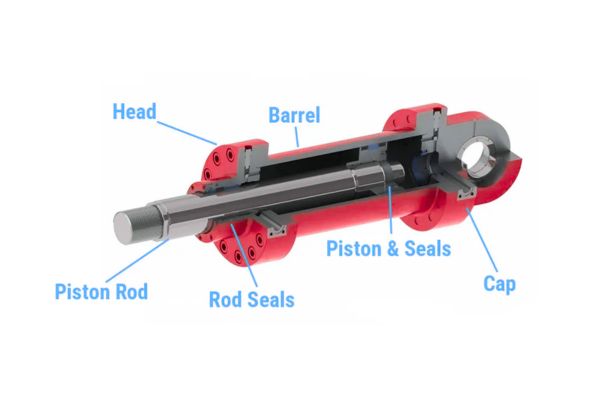
How Do Internal Components Synchronize to Execute Linear Force?
A functional fluid power actuator relies on a sequence of internal heavy steel parts and high-durometer dynamic seals working in perfect synchronization. If any single component suffers surface scoring or physical wear, the entire mechanical system loses its structural capacity to hold or lift load.
What Roles Do Piston Rods and Bore Surfaces Play in Motion?
The internal piston works as the primary physical barrier that splits the honed barrel into two separate high-pressure zones: the cap end and the rod end. As pressurized oil pumps into either side, the piston slides smoothly along the internal bore surface, driving the attached chrome-plated rod out into open space. The rod itself must be machined from high-tensile carbon steel, ground to precise mirror finishes, and induction hardened to resist structural flexing under full extension.
You must track how these moving components interact during a standard operational cycle:
- The internal piston: Separates opposing pressure chambers while guiding linear travel.
- The polished rod: Transmits raw internal hydraulic thrust out to the external implement.
- The honed bore surface: Provides a flawlessly smooth track for dynamic rubber seals.
How Do Dynamic Seal Configurations Prevent Catastrophic Bypass?
You can have the strongest steel barrel on the market, but without a high-performance dynamic seal package, your actuator is completely useless. The piston is wrapped in heavy-duty, multi-piece polyurethane seals backed by tough nitrile wear rings that block oil from sneaking across opposing pressure chambers. Simultaneously, the rod gland contains a robust U-cup seal and a hard scraper wiper designed to trap high-pressure oil inside while knocking field dirt off the returning chrome rod.
- Primary piston seals: Multi-stage polyurethane rings block internal fluid from cross-bypassing.
- Wear guide bands: High-density nylon rings absorb severe side loads and prevent metal-on-metal scoring.
- Rod wiper seals: Tough outer scrapers shed mud, ice, and field dust during high-speed retraction.
Why Does the Head Gland Assembly Manage Structural Alignment?
The heavy steel head gland works as the absolute structural guide for the extending chrome rod, holding it in perfect linear alignment with the center axis of the barrel. It houses the critical rod seals, wear rings, and retention threads, meaning it takes the brunt of any lateral offset forces during operation. If this crucial alignment hub experiences thread loosening or bearing wear, the rod will cock out of square, immediately destroying internal seals.
- Radial constraint: Keeps the high-tensile rod moving on a perfectly straight center path.
- Seal preservation: Prevents off-center side loads from distorting delicate rubber lips.
- Pressure retention: Pins the dynamic rod seal package securely against high pressure spikes.
| Component Name | Primary Material | Critical Operational Function |
|---|---|---|
| Honed Actuator Barrel | ST52.3 Cold Drawn Steel Tubing | Encloses high-pressure fluid without wall distortion |
| Induction Hardened Rod | CK45 Hard Chromed Carbon Steel | Transmits raw linear thrust to external machinery linkages |
| Dynamic Piston Seal Pack | Polyurethane 92 Shore A / Nitrile | Blocks high-pressure fluid from cross-chamber bypassing |
What Defines the Mechanical Difference Between Cylinder Variants?
You will find that heavy industrial machinery utilizes two primary styles of fluid actuators depending on the level of operational control needed. Choosing between single and double-acting designs dictates how your hydraulic system manages return routing and system pressure balance.
How Do Single-Acting Units Leverage External Forces for Return?
Single-acting cylinders use hydraulic power in only one direction, relying on heavy internal springs or external gravity loads to push the rod back down. Pressurized oil enters a single port to extend the piston, and when the control valve shifts, the internal pressure exhausts back to the reservoir as the weight of the implement forces the rod to retract. These units are highly common in basic vertical lift platforms, hydraulic truck jacks, and simple agricultural implements where complex bi-directional control is unnecessary.
- Single port input: Hydraulic fluid drives motion exclusively during the extension stroke.
- Mechanical retraction: Heavy internal springs or gravity loads force the fluid back out.
- Simplified plumbing: Eliminates secondary return lines, reducing potential valve leaks.
Why Do Double-Acting Designs Deliver Precision Bi-Directional Power?
When your job site demands absolute precision during both pushing and pulling operations, double-acting engineering becomes vital. These advanced units feature independent fluid ports at both ends of the barrel, allowing your control valves to pump high-pressure oil to either side of the internal piston. This design guarantees you have full hydraulic power during extension and retraction, which is essential for steering links, excavator boom arms, and industrial molding presses.
- Dual port control: Independent hydraulic lines manage both sides of the internal piston.
- Balanced bi-directional force: Pumping fluid to the rod end provides active pulling power.
- Total velocity management: Control valves throttle oil flow out of the exhausting port to smooth travel.
| Actuator Category | Fluid Port Count | Primary Return Mechanism |
|---|---|---|
| Single-Acting Design | 1 Dedicated Inlet Port | External implement weight or heavy internal springs |
| Double-Acting Design | 2 Opposing Fluid Ports | Active hydraulic pressure switched via control valves |
How Does Fluid Velocity Directly Control Stroke Positioning Precision?
Managing the exact operating speed and stopping position of a heavy load requires precise control over the hydraulic fluid entering the cylinder barrel. You must track how fluid volumetric flow rates shape internal speed and how specialized terminal cushioning dampens heavy mechanical impacts.
What Happens When Internal Flow Volumetric Rates Fluctuate Unexpectedly?
The speed of an extending piston rod depends entirely on the volume of hydraulic oil pumped into the cylinder per minute, not the system pressure. If your engine pump delivery fluctuates or an internal valve begins to stick, the fluid velocity inside the barrel turns erratic, causing heavy loader implements to shudder or lag. To maintain smooth, linear travel under varying field conditions, you must use pressure-compensated flow control valves to stabilize fluid delivery.
You can calculate exact stroke speed by tracking how input flow interacts with internal cylinder dimensions:
{Velocity} ={Flow Rate}/{Piston Area}
If you change the input flow without adjusting the internal piston surface area, your rod travel speed will instantly shift out of spec.
- Volumetric consistency: Stable oil delivery guarantees predictable implement travel speed.
- Pressure independence: System load variations change working pressure, not rod speed.
- Valve synchronization: Proportional flow controls prevent sudden hydraulic lurching.
How Do Built-In Cushioning Mechanisms Prevent Destructive Piston Impact?
When a massive excavator arm extends at full velocity, the heavy steel piston carries immense kinetic energy that can crack end caps upon terminal impact. To stop this metal-on-metal slamming, high-performance actuators use built-in cushioning spears that restrict the exhaust port just before the end of the stroke. This restriction creates a dense cushion of high-pressure oil that smoothly slows the piston down, protecting your structural welds from severe shock fatigue.
- Cushioning spear engagement: A tapered nose enters the exhaust port to slow exiting fluid.
- Localized backpressure: Restricted exhaust paths rapidly build a dynamic fluid braking zone.
- Structural shock mitigation: Trapped oil absorbs terminal kinetic energy before metal contacts metal.
+-------------------------------------------------------------+
|                TERMINAL EXPULSION CUSHIONING                 |
|                                                             |
|   Piston Travel =====> [ Cushioned Spear Enters Port ]      |
|                                     |                       |
|                                     v                       |
|                        Restricted Fluid Escape              |
|                                     |                       |
|                                     v                       |
|                        High Deceleration Backpressure       |
+-------------------------------------------------------------+
What Diagnostic Procedures Isolate Internal Fluid Bypass Failures?
When a heavy industrial machine begins to drift or lose holding power under full load, you must execute precise isolation tests to find the hidden failure point. Let us explore exactly how internal fluid bypass breaks down machine stability and how field mechanics diagnose these hidden seal failures without specialized shop tools.
Why Does Steering Cylinder Internal Leakage Induce Unintentional Drift?
If you notice your tractor slowly wandering off course during straight field runs, the root cause is almost always tractor steering cylinder internal leakage. When the internal piston seals wear thin, high-pressure oil slowly bypasses the piston face, sneaking into the opposing low-pressure chamber. This internal pressure loss unbalances the hydraulic circuit, causing the steering links to slowly move even when your hands are off the steering wheel.
- Loss of holding torque: Implements drift down under load because the cylinder cannot trap pressure.
- Asymmetric steering wheel response: The machine takes more steering wheel rotations to turn one way.
- Spike in heat generation: Bypassing oil generates severe friction, raising system temperatures.
How Do Field Technicians Validate Piston Seal Degradation Safely?
To prove that your internal piston seals are shot without removing the cylinder, you must perform a standard manual isolation bypass test. First, extend the actuator completely to its dead-stop limit, shut down the engine, and safely lock the heavy mechanical links in place to prevent sudden drop. Next, carefully unhook the return hydraulic hose from the retraction port, place it over a clean bucket, and re-pressurize the extension circuit.
If oil starts streaming out of that open retraction port, your piston seals are completely blown and allowing fluid bypass.
- Port isolation sequence: Unhooking the return line instantly separates the internal pressure zones.
- Bypass visual validation: Continuous oil flow from an open port confirms internal seal failure.
- Pressure gauge comparison: Low pressure on a dead-stop circuit points to internal cross-bleeding.
| Observed Symptom | Hidden Root Cause | Immediate Field Corrective Action |
|---|---|---|
| Implements slowly drift down | Piston seal bypass from wear | Execute open-port isolation test; replace seal package |
| Erratic or spongy stroke travel | Trapped air inside the barrel | Run full stroke cycles lock-to-lock to bleed the air out |
| External fluid at the rod gland | Blown rod U-cup packing | Unthread head gland; install fresh polyurethane rod seals |
How Do Corrosive Environmental Stresses Compromise Rod Surfaces?
The polished chrome rod extending from your cylinder barrel is constantly exposed to harsh agricultural fertilizer splashes, abrasive mud, and rock impacts. You must track how microscopic surface corrosion rapidly destroys internal seals and what maintenance steps shield your metal investments from pitting.

Why Does Microscopic Plating Degradation Precipitately Destroy U-Cups?
Every time a corroded rod retracts, its rough surface acts like a metal file, tearing up the delicate lips of your internal polyurethane rod seals. If the thin chrome plating suffers rock dings or acidic fertilizer etching, deep microscopic pits quickly form along the bare steel core. As the rod cycles through the head gland, these sharp pits cut the internal U-cup seal, causing external oil leaks and sudden system pressure drops.
- Abrasive friction: Rust pits slice the sealing edge of your internal rubber packings.
- Contaminant carry-in: Deep surface pits carry field dust past the rod wiper seal.
- Chrome flaking: Compromised plating peels back, exposing raw steel to deep rust.
What Maintenance Practices Shield Hard Chrome Plating From Pitting?
To save your dynamic seals from abrasive wear, you must implement a strict rod cleaning and storage routine. If your machinery sits idle for extended periods, always park the equipment with the cylinder rods fully retracted so they stay immersed in a protective coat of hydraulic oil. When rods must remain extended outdoors, coat the exposed chrome with heavy-duty anti-corrosion grease or use premium neoprene protective boots to shed abrasive field dirt.
- Seasonal storage habits: Retract all rods fully to shield bare metal from humid weather.
- Chemical neutralizers: Wash down your cylinders thoroughly after applying acidic fertilizers.
- Protective greasing: Application of a thin grease coat stops oxidation on extended rods.
The following field-proven maintenance schedule will drastically reduce your seasonal component repair bills.
+-------------------------------------------------------------+
|                SURFACE PROTECTION WORKFLOW                  |
|                                                             |
|   Exposed Chrome Rod ----> [ Post-Application Washdown ]    |
|                                      |                      |
|                                      v                      |
|                        Neutralize Acidic Fertilizers        |
|                                      |                      |
|                                      v                      |
|          [ Retract Rod for Storage ] or [ Coat With Grease ]|
+-------------------------------------------------------------+
What Engineering Forces Precipitate Structural Piston Rod Bending?
A bent piston rod will permanently lock up a hydraulic actuator, warping internal wear bands and causing immediate, catastrophic fluid loss. You must look past nominal pressure ratings to understand how offset lateral forces twist high-tensile steel rods out of spec.
How Do Offset Loading Vectors Generate High Bending Moments?
The single most destructive threat your actuator rods encounter in the field is side loading, which happens when external forces push out of square with the cylinder’s linear path. Piston rods are explicitly engineered to handle immense compression and tension along their center axis, but they have very little defense against lateral bending forces. If you use a front loader bucket to pry sideways against a buried rock, the off-center load instantly creates a high bending moment that warps the extended rod.
- Axial misalignment: Off-center loads concentrate severe stress on one side of the rod.
- Gland binding: A warped rod binds against the head gland, causing severe operational drag.
- Piston distortion: Bent rods force the internal piston to edge-ride and score the bore.
Why Do Worn Pin Bushings Compromise True Linear Cylinder Geometry?
You must realize that the heavy mounting pins and bushings at each end of your hydraulic cylinder are the only components keeping your actuator aligned under load. If the mounting pins get sloppy or wear into an oval shape, the cylinder loses its tight radial constraint and begins to twist out of square under pressure. This tiny geometric shift forces the actuator to operate with a continuous side load, bending the rod long before you ever hit rated pressure limits.
- Mounting joint play: Sloppy pins allow the cylinder barrel to twist off-center.
- Asymmetric stress: Off-axis movement forces internal wear rings to overload and fail.
- Structural fatigue: Loose linkages amplify mechanical shock loads during rapid directional changes.
+-------------------------------------------------------------------------+
|                    STRUCTURAL FAILURE RISK ANALYSIS                     |
+-------------------+--------------------+--------------------------------+
| Mechanical Root   | Component Risk     | Long-Term Structural Solution  |
| Cause             | Threshold          |                                |
+-------------------+--------------------+--------------------------------+
| Ovaled mounting   | Over 0.5mm pin     | Ream out mounting ears; press  |
| bore joints       | tolerance slop     | in hardened steel bushings     |
+-------------------+--------------------+--------------------------------+
| Lateral side      | Off-axis loading   | Install heavy-duty spherical   |
| loading forces    | vectors            | rod-end bearings for pivot     |
+-------------------+--------------------+--------------------------------+
How Does Operational Temperature Flux Change Component Reliability?
Operating heavy industrial equipment in extreme weather requires a deep understanding of how fluid temperature changes affect your system components. Let us examine how winter cold starts compromise your rubber seals and how summer oil breakdown accelerates internal fluid bypass.
What Happens to Low-Temperature Compound Seals on Winter Cold Starts?
When you start up a tractor in sub-zero winter temperatures, the dynamic polyurethane seals inside your cylinders turn brittle and lose their elastic flexibility. If you immediately cycle your valves under heavy load without warming up the oil, the rigid seal lips cannot flex to match pressure shifts, causing instant fluid leaks and deep scoring. To protect your system, you must run your machinery at idle to cycle warm oil through the circuits before lifting heavy loads.
- Loss of seal elasticity: Brittle rubber cracks when subjected to sudden pressure spikes.
- Breakaway friction spikes: Cold, thick oil raises initial sliding resistance.
- Wiper lip splitting: Frozen mud on the rod can tear rigid scraper seals on the first stroke.
How Does Thermal Oil Breakdown Amplify Internal Bypassing Velocity?
On the flip side, operating heavy equipment for hours in scorching summer heat causes hydraulic oil temperatures to skyrocket, cutting fluid viscosity below safe design limits. As the oil thins out, it slips past worn internal piston seals much faster, causing implements to drift downward and lose lifting speed mid-day. Thin, overheated oil also fails to maintain a protective lubrication film on the interior bore, accelerating internal metal-on-metal wear.
- Fluid viscosity drop: Thin, overheated oil slips easily past dynamic seals.
- Accelerated seal aging: Long exposure to hot oil bakes rubber seals until they turn hard.
- Loss of system control: Slippery, low-viscosity oil reduces total positioning precision.
+-------------------------------------------------------------+
|                 THERMAL FLUX RISK WORKFLOW                  |
|                                                             |
|   Extreme Cold Start ----> [ Rigid Brittle Seals ]          |
|                                     |                       |
|                                     v                       |
|                        Sudden Pressure Spike                |
|                                     |                       |
|                                     v                       |
|           [ Cracked Seal Lips ] ----> Catastrophic Oil Leak |
+-------------------------------------------------------------+
Conclusion
This technical framework targets the core engineering realities of high-pressure fluid power infrastructure. By addressing the physical properties of hydrostatic force, step-by-step diagnostic workflows, and precise geometric procurement checks, this guide provides a direct solution to the real-world operational challenges that lead to equipment downtime. We are committed to building long-term global trade partnerships that deliver resilient fluid power components to the world’s most demanding agricultural, construction, and heavy industrial fleets. For direct engineering consultations or to review component test certifications for your specific fleet infrastructure, please contact us today.
FAQ
Can I drive my machinery with a slight fluid weep at the head gland?
No, a head gland weep can let dirt enter the cylinder and quickly turn a simple seal issue into barrel damage.
What’s the best way to measure stroke length on an unmarked cylinder?
Measure the pin-to-pin length when fully retracted and fully extended, then subtract the retracted length from the extended length.
How do I know if my cylinder is drifting from internal bypass or valve failure?
Isolate the cylinder from the control valve; continued drift usually means piston seal bypass, while stopped drift points to valve leakage.
Can I straighten a slightly bent piston rod using a shop press?
No, a bent piston rod should be replaced because hidden runout can damage the gland and cut new seals.
How do I safely bleed trapped air out of a newly installed actuator?
Cycle the actuator slowly through its full stroke under no load until movement becomes smooth and air noise disappears.