How To Select The Right Hydraulic Cylinder Component For Replacement
Selecting the right hydraulic cylinder component for replacement requires a precise understanding of your system operating pressure, stroke speed, and environmental conditions to avoid premature seal failure or rod scoring. A sudden pressure drop in your heavy machinery can halt an entire production line. You watch fluid leak from a worn seal, knowing every minute of downtime costs thousands of dollars. We provide heavy-duty engineering solutions and high-precision fluid power alternatives to keep your systems operating under the most demanding industrial conditions.
How Do Environmental Conditions Impact Seal Selection?
Extreme temperatures and corrosive chemical exposure dictate the base polymer choice for any internal sealing element. Operating a system with mismatched seal chemistry guarantees rapid material degradation and external fluid leakage.

Analyze Extreme Operational Temperatures
High thermal exposure breaks down standard nitrile compounds, turning them brittle and causing micro-cracking along the sealing lip. Conversely, sub-zero environments cause standard materials to lose elasticity and fail to maintain critical radial tension.
- Fluorocarbon seals withstand continuous operating temperatures exceeding 200 degrees Celsius without losing structural integrity.
- Low-temperature nitrile formulations maintain necessary flexibility down to minus 40 degrees Celsius for outdoor mobile equipment.
- Consistent thermal monitoring prevents localized fluid overheating from destroying internal piston seals prematurely.
Thermal breakdown accounts for a massive percentage of early fluid power system failures in heavy manufacturing environments.
Assess Chemical And Corrosive Exposure
Outdoor marine environments or industrial chemical processing plants introduce aggressive corrosive elements that attack exposed metal surfaces and sealing polymers. Protecting the structural integrity of your internal parts requires specialized chemical compatibility assessments.
- Viton compounds resist chemical breakdown when exposed to synthetic fire-resistant hydraulic fluids.
- Stainless steel rod attachments prevent localized pitting corrosion from tearing through rod seals during retraction.
- Aggressive ambient dust requires heavy-duty scraping wipers to prevent particulate ingestion into the main gland.
Corrosive pitting on an unhardened rod acts like a saw blade, destroying your sealing elements within a few operational cycles.
| Seal Material | Temperature Range | Chemical Compatibility |
|---|---|---|
| Standard Nitrile (NBR) | -30°C to +100°C | Mineral Oils, Water-Glycol Fluids |
| Fluorocarbon (Viton) | -20°C to +200°C | Synthetic Fluids, Aggressive Chemicals |
What Rod Material Coating Minimizes Surface Corrosion?
Hard chrome plating with appropriate thickness or advanced laser cladding provides the necessary hardness to resist abrasive wear and atmospheric corrosion. Exposed piston rods face constant impact from debris and moisture during normal operation.
Compare Hard Chrome Plating Thickness
Standard industrial applications rely on conventional hard chrome plating to provide a smooth, durable surface layer that reduces friction and resists scratching. The thickness of this layer determines its long-term resistance to impact and environmental moisture.
- Engineered components feature chrome plating thickness between 25 and 50 microns for optimal durability.
- Micro-cracking inherent in chrome plating can allow moisture to reach the base metal if not properly managed.
- Induction hardening before plating increases impact resistance against flying rocks or mechanical contact.
Inadequate plating thickness allows sub-surface rust to form, lifting the chrome layer and ruining the seal surface.
Review Nitriding And Alternative Coatings
Severe marine or chemical environments require superior corrosion resistance that exceeds the capabilities of traditional chrome plating. Advanced surface treatments alter the base metal properties or add ultra-dense protective barriers.
- Ferritic nitrocarburizing produces an iron nitride layer that resists salt spray corrosion exceptionally well.
- Laser cladding applies an ultra-dense layer of nickel-based alloy for extreme environmental resistance.
- Ceramic coatings offer unmatched hardness and corrosion barriers for specialized offshore drilling equipment.
Altering the surface chemistry through nitriding eliminates the risk of coating delamination under extreme mechanical stress.
| Coating Type | Surface Hardness | Salt Spray Corrosion Resistance |
|---|---|---|
| Hard Chrome Plating | 850 – 1000 HV | Moderate (100 – 500 Hours) |
| Nitrocarburizing (QPQ) | 700 – 900 HV | High (Up to 1000 Hours) |
How Do You Determine The Exact Stroke Length?
Accurate measurement between the fully extended and fully retracted pin centers prevents mechanical bottoming and structural weld failure. Incorrect stroke specifications cause severe internal impact damage or prevent full equipment articulation.
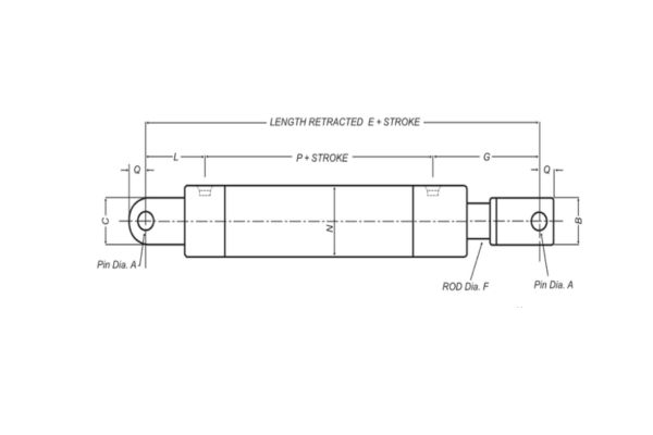
Verify Physical Installation Dimensions
Measuring a damaged or completely retracted unit requires verifying the distance between mounting hole centers to ensure drop-in compatibility. You must account for any external accessories or specialized sensor mountings that alter the physical footprint.
- Dead length calculations must include the thickness of the piston, gland, and internal stop tubes.
- Retracted length verification prevents the unit from striking structural frames before reaching full travel.
- Pin-to-pin dimensions must match your original equipment manufacturer blueprints exactly to maintain correct leverage.
Calculate Stop Tube Requirements For Long Strokes
Long-stroke cylinders operating under heavy compressive loads face significant risk of structural buckling and excessive lateral bearing wear. Implementing internal mechanical spacers mitigates these forces by increasing the distance between the piston and gland bearings.
- Strokes exceeding 1,000 millimeters require careful evaluation of internal bearing separation distances.
- Stop tubes prevent the piston from traveling to the absolute end of the barrel, stabilizing the extended rod.
- Dual-piston configurations can also be utilized to handle intense side-loading without bending the main rod.
| Stroke Parameter | Minimum Boundary | Maximum Structural Limit |
|---|---|---|
| Standard Stroke | 50 mm | 1,000 mm (Without Stop Tube) |
| Long-Stroke Compressive | 1,000 mm | Evaluated via Euler Buckling Criteria |
What Mounting Style Handles Your Specific Load Direction?
Rigid flange mounts support pure axial thrust along the centerline, whereas pivot mounts allow mechanical self-alignment for shifting non-axial loads. Selecting an improper mounting design induces severe side-loading that quickly destroys bearings and seals.
Implement Clevis And Trunnion Pivot Mounts
Applications involving curved motion paths or pivoting mechanical linkages require mounts that articulate freely to absorb changing angles. These designs reduce bending stresses on the piston rod by allowing the body to move with the load.
- Rear clevis mounts allow rotational freedom in a single plane for standard dumping mechanisms.
- Trunnion mounts utilize specialized pins located on the head, cap, or intermediate body positions for balanced pivoting.
- Spherical bearing mounts accommodate multi-directional misalignment caused by structural deflection under load.
Utilize Rigid Flange And Tie-Rod Mounts
Stationary industrial machinery like hydraulic presses or heavy stamping equipment utilizes rigid mountings to lock the hydraulic cylinder firmly against a solid platen. These configurations transfer immense axial force directly into the machine frame.
- Head flange mounts handle high tensile loads during the retraction stroke of heavy pressing operations.
- Cap flange mountings excel at absorbing massive compressive forces during full forward extension.
- Foot mounts bolt parallel to the centerline but require proper pinning to resist high shear stresses at the base.
| Mount Classification | Primary Load Vector | Misalignment Tolerance |
|---|---|---|
| Clevis / Trunnion (Pivot) | Centerline Axial / Shifting Plane | Moderate to High (1 – 3 Degrees) |
| Head / Cap Flange (Rigid) | Centerline Axial / Fixed Plane | Strict Zero Tolerance |
What Cushioning Options Prevent High-Impact End-Of-Stroke Damage?
Adjustable internal cushions decelerate the piston smoothly before it strikes the heavy steel end caps, preventing structural fracturing and severe system vibration. Uncushioned high-speed impacts cause severe metal fatigue over millions of operational cycles.
Analyze High-Speed Deceleration Needs
Systems operating at linear speeds exceeding 0.1 meters per second experience massive kinetic energy transfer when the piston reaches the end of its travel. Internal deceleration mechanisms throttle the exiting fluid to slow the load down safely.
- Progressive spear profiles restrict the fluid exit path gradually for smooth deceleration tracking.
- Check valves allow full fluid flow into the piston area for rapid acceleration during stroke reversal.
- Hardened steel cushion sleeves resist erosion caused by high-velocity fluid throttling at the end-of-stroke.
Without effective deceleration, the constant hammering of the piston against the head cap will crack the mounting bolts.
Adjust Needle Valves For Variable Loads
Industrial machinery handling variable load weights requires adjustable throttling to tune the deceleration profile precisely. Needle valves located on the cylinder caps allow maintenance technicians to optimize backpressure based on current operating conditions.
- Turning the needle valve clockwise increases backpressure, slowing heavy loads down more aggressively.
- Locknuts prevent the adjusted needle valve from shifting position due to continuous machine vibration.
- Internal relief valves can supplement cushions to prevent localized pressure spikes from bursting the barrel.
Over-tightening the cushion needle valve can create an internal pressure lock that stops the machine from completing its cycle.
How Do Port Sizes And Connection Styles Affect Flow Velocity?
Selecting oversized ports slows fluid entry, while restrictive ports cause high fluid velocity, localized heat generation, and severe pressure drops across the connection. Maintaining correct flow dynamics keeps your cycle times predictable.

Compare SAE Straight Thread O-Ring Ports
Modern high-pressure fluid power systems rely on SAE straight thread O-ring connections to provide reliable, leak-free operation under intense pressure cycling. These ports utilize an elastomeric seal compressed within a machined chamfer.
- SAE straight threads eliminate the risk of split-port castings caused by over-tightening tapered threads.
- Machined sealing surfaces prevent fluid weeping even during heavy mechanical vibration.
- Compact designs allow multiple ports to be clustered together on custom multi-stage manifolds.
Tapered NPT threads are highly prone to weeping and often split the cylinder head if over-torqued during maintenance.
Review Four-Bolt Flange Connections
High-flow industrial machinery requires massive port paths to move large volumes of fluid without generating excessive restrictive heat. Heavy-duty flange connections bolt directly to the cylinder body to provide maximum structural support.
- Code 61 flanges handle standard industrial pressures up to 3,000 PSI with excellent high-flow capacity.
- Code 62 flanges feature thicker walls and larger bolts to manage intense 6,000 PSI operations safely.
- O-ring seals embedded in the flange face compress perfectly against the flat machined cylinder surface.
Flanged connections allow technicians to remove heavy hoses without twisting large, rigid line fittings during field replacement.
What Piston Design Prevents Fluid Bypass Under Heavy Load?
Multi-piece piston assemblies with heavy-duty wear bands prevent metal-to-metal contact with the honed barrel, ensuring complete sealing efficiency during pressure holds. Single-piece unguided designs slip and score the inner walls under side-loading.
Evaluate Wear Band Material Composition
Side loads applied to the extended piston rod force the internal piston to press hard against the inner walls of the steel barrel. Non-metallic wear bands absorb these lateral forces, protecting the expensive honed finish from scratching.
- Glass-filled nylon wear bands offer high compressive strength for heavy-duty construction equipment.
- Phenolic resin bands handle extreme impact loads and absorb small particulate contaminants safely.
- PTFE-blended wear rings reduce starting friction, eliminating erratic slip-stick movement during slow operation.
Implement Multi-Piece Sealing Groups
High-pressure holding applications require zero-leakage piston configurations to prevent drifting loads from compromising workplace safety. Combining multiple specialized sealing elements onto a single piston hub achieves this performance milestone.
- Energized elastomeric rings expand outward to seal completely even under low-pressure conditions.
- Tough outer slide rings resist extrusion into the clearance gaps when system pressure hits maximum limits.
- Active anti-extrusion rings protect the main sealing element from tearing under high thermal expansion.
How Do You Calculate The Correct Bore Diameter For Lifting?
Determining the exact inner barrel surface area ensures your system generates sufficient force to lift heavy industrial loads at specified pressures. Specifying an inadequate bore diameter prevents your machinery from handling its rated payload capacity.
Apply The Basic Fluid Power Force Equation
Calculating the required force requires multiplying the system operating pressure by the cross-sectional area of the inner barrel. This calculation must account for internal mechanical friction and upstream pressure drops through the valves.
F=P×A
- Bore area calculations use the square of the internal radius multiplied by pi.
- Retraction force is always lower because the internal rod reduces the effective piston area.
- Designing a twenty percent safety margin into your force calculations prevents stalling under unexpected loads.
Account For Rod Displacement During Retraction
The volume of steel occupied by the piston rod reduces the available fluid volume inside the head end of the hydraulic cylinder barrel. This displacement speeds up retraction times but reduces the total pulling force your machine can exert.
- Large-diameter rods provide excellent column strength but significantly reduce net pulling capability.
- System designers must calculate both extension and retraction forces to verify overall machine performance.
- Matching pump flow to the reduced retraction volume prevents sudden fluid cavitation in return lines.
Conclusion
The core data analyzed across these technical parameters confirms that selecting a high-precision hydraulic cylinder component demands matching specific material properties to your operational realities to prevent early failure.
If you face recurring fluid bypass, rod scoring, or premature seal breakdown, your current specifications are likely mismatched to your operating environment. Contact us today to have our application engineers review your technical system parameters and source the exact high-precision component your machinery requires. We engineer fluid power solutions that eliminate industrial downtime.
Frequently Asked Questions
Can I replace a single internal seal or should I swap out the entire gland assembly?
You can replace individual seals if the metal gland shows zero signs of scoring or bore wear. If the internal bronze bearing surfaces show significant wear or ovality, you must replace the entire gland assembly to prevent immediate failure of your new seals.
What’s the best way to identify an unknown thread style on an old cylinder port?
The best approach involves using a digital caliper to measure the outside thread diameter alongside a pitch gauge to count the threads per inch. Compare these physical measurements against standard SAE, NPT, and BSPP technical charts to identify the connection profile safely before ordering replacement fittings.
How do I know if my cylinder rod is bent without specialized laboratory tools?
You can perform a quick field check by extending the rod fully and placing a precision machinist straightedge along the chrome surface. Spin the rod 360 degrees while checking for visible light gaps between the straightedge and the steel bar to identify any significant structural bending.
Can I use a standard chrome-plated rod in an offshore marine application?
You can use it only if the system operates intermittently and receives constant manual lubrication. For continuous salt spray exposure, you must upgrade to a specialized nickel-chrome clad rod or a nitrided surface treatment to prevent severe pitting corrosion from destroying the main seals.
How do I stop a heavy cylinder from drifting when the control valve is in neutral?
You must install a pilot-operated check valve directly onto the ports to lock the fluid inside the barrel mechanically. Internal fluid bypass across worn piston seals can cause drift, but adding external locking valves completely isolates the unit from spool leakage inside the main control manifold.