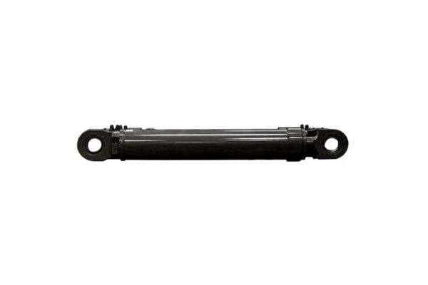
How to Diagnose Leaks with A Hydraulic Cylinder Maintenance Checklist
You pull into the facility on Monday morning only to find a pool of industrial fluid spreading across the concrete floor beneath your primary production machinery. A critical cylinder has lost pressure overnight, causing a costly assembly line stoppage, missed delivery deadlines, and climbing labor costs. You need a fast diagnostic method to fix this issue and prevent it from happening again. Utilizing a professional hydraulic cylinder maintenance checklist allows facility maintenance teams to identify internal or external fluid bypass areas systematically before a catastrophic component failure halts your entire business operation.
Why Do Industrial Hydraulic Systems Experience Severe Internal Bypass?
Fluid bypass occurs when damaged internal sealing elements allow high-pressure oil to slip past the piston into the low-pressure return side of your system. This internal migration drastically reduces the total mechanical force your equipment can generate, which slows down cycle times and creates immense thermal heat build-up within the system reservoir.
Are Worn Piston Seals The Core Cause Of Loss Of Force?
Worn or degraded piston seals represent the absolute primary source of internal pressure loss in industrial machinery. When these internal elastomer components break down, the oil bypasses the piston head completely during the stroke cycle.
- Contaminated hydraulic oil scratches the internal barrel surface and cuts thin grooves into the piston seal material.
- Severe chemical degradation from high operating temperatures hardens the rubber compound and destroys its flexibility.
- Extreme pressure spikes stretch the cylinder body slightly, allowing oil to escape through the resulting gap.
- Incorrect installation practices can nick or twist the sealing lip during assembly, causing an immediate drop in pressure.
Can Mechanical Side Loading Accelerate Internal Fluid Leakage?
Mechanical misalignment creates severe side loading forces that push the piston assembly unevenly against one side of the internal steel barrel wall. This uneven physical force deforms the guide rings rapidly and allows the piston seal to ovalize.
- Improper machine leveling forces the rod to travel along an unaligned path during operation.
- Heavy eccentric loads pull the rod downward, crushing the internal wear bands over time.
- Loose mounting bolts allow the cylinder base to shift under high pressure cycles.
| Mechanical Symptom | Primary Internal Root Cause | Corrective Maintenance Action |
| Drastic Loss of Push Force | Destroyed Piston Seals | Replace Seals and Flush Hydraulic Fluid |
| Rapid Localized Heat Generation | High Velocity Oil Bypass | Reseal Piston and Inspect Internal Barrel |
| Uneven Rod Wear Patterns | Severe Structural Side Loading | Realign Machine Mounts and Replace Guide Rings |
How Do You Safely Isolate A Pressurized Cylinder For Inspection?
Working on high-pressure fluid systems poses severe safety risks if the internal energy is not completely dissipated before your technicians begin handling the component fittings. Failing to execute proper safety isolation can cause accidental system movement, severe fluid injection injuries, or sudden mechanical collapse.
Why Must You Fully Extend The Rod Before Depressurization?
You must fully extend or completely retract the piston rod to eliminate trapped fluid volumes inside the cylinder chambers before opening any hydraulic connections. This physical positioning ensures no mechanical energy remains stored within the system.
- Gravity can cause un-supported heavy machine components to drop suddenly when lines are loosened.
- Trapped thermal expansion pressure can spray hot oil outward if a fitting is cracked open prematurely.
- Dual-acting circuits can hold dangerous pressure on both sides of the piston simultaneously.
- Internal pilot-operated check valves can trap high pressure even when the main control valve is open.
What Steps Safely Release Residual Fluid Power Energy?
Simply turning off the main electrical power switch to the hydraulic pump motor does not completely remove the dangerous residual fluid pressure stored inside your system accumulators or lines. Technicians must manually actuate the control valves multiple times to bleed all remaining pressure back to the reservoir tank safely.
- Shut down the electric motor and lock out the main electrical disconnect switch properly.
- Cycle all manual directional control valve levers through their full range of motion.
- Check the system pressure gauges to verify that the pressure reading reads exactly zero PSI.
| Isolation Step | Required Tooling | Expected Safety Outcome |
| Electrical Lockout | Padlock and Safety Tag | Prevents Accidental Pump Motor Activation |
| Valve Cycling | Manual Control Levers | Bleeds Trapped Pressure to the Oil Reservoir |
| Gauge Verification | Calibrated Fluid Pressure Gauge | Confirms Zero Energy State Before Disassembly |
What External Leakage Points Require Immediate Technical Attention?
External fluid leaks are highly visible indicators of system degradation that ruin workplace safety by creating slick floors and increasing your total operational oil consumption expenses. Identifying the precise location of an external leak helps pinpoint exactly which external sealing component has failed.
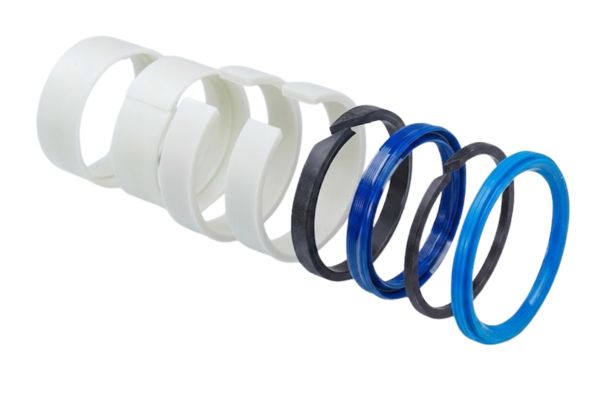
Is The Rod Seal The Main Culprit For External Puddles?
The rod seal is the most vulnerable external sealing component because it is constantly exposed to external environmental contaminants and continuous physical friction. A damaged rod seal allows fluid to weep out of the cylinder head gland during every single extension stroke.
- Microscopic ambient dust particles adhere to the wet rod and tear the seal lip during retraction.
- High operating pressure pushes the seal material into the gland clearance gap, causing extrusion failure.
- Corrosive chemical airborne vapors attack the polyurethane seal material, causing it to crack.
- Excessively dry operating conditions increase friction forces, scorching the seal lip material.
How Do Scorched Gland O-Rings Cause Fluid Seepage?
The static O-ring located between the hydraulic cylinder head gland and the main steel barrel sleeve can fail due to localized overheating or excessive physical vibration. This failure results in a steady drip of oil running down the outside body of the cylinder.
- Constant high-frequency system vibrations back off the threaded gland cap over time.
- Extreme thermal cycling hardens the static nitrile rubber O-ring, causing it to lose its elasticity.
- Over-tightening the gland during rebuilds pinches and cuts the static rubber seal compound.
| External Leak Location | Most Common Root Cause | Best Preventive Action |
| Front Rod Gland Cap | Torn Polyurethane Rod Seal | Install Heavy Duty Excluder Wiper Seal |
| Barrel Thread Junction | Pinched Static Gland O-Ring | Replace O-Ring and Torque Gland to Specification |
| Hydraulic Port Fitting | Cracked Flange Weld or Stripped Thread | Re-weld Port or Replace Fitting with O-Ring Boss |
How Do You Inspect Piston Rods For Critical Structural Defects?
The piston rod acts as the main mechanical link that transfers raw fluid power into physical linear movement for your heavy industrial machinery. Any surface imperfection or structural bending along the rod will quickly destroy new seals and cause sudden component locking.
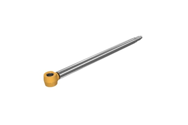
Can Bending Micro-Defects Destroy New Replacement Seals?
Operating a bent piston rod creates severe, uneven physical clearance gaps inside the cylinder head gland assembly. This structural distortion places intense localized pressure on one side of the rod seal, causing it to fail within a few operating hours.
- Overloading the machine beyond its rated mechanical capacity bends the steel rod structure.
- Accidental physical impacts from heavy external factory equipment dent the exposed rod surface.
- Long-stroke cylinders operating horizontally sag under their own physical weight without support.
Why Are Chrome Pitting And Deep Scratches Dangerous?
Tiny pits or deep longitudinal scratches in the hard chrome plating act like miniature saw blades that shred the delicate rubber sealing lips every time the rod retracts into the cylinder. Inspecting the surface finish helps stop seal degradation before it starts.
- Flying welding slag or abrasive shop sparks melt small holes into the chrome plating.
- Corrosive ambient moisture or saltwater spray pits the underlying steel through chrome pores.
- Hard particulate contamination trapped in the wiper seal scores deep tracks along the rod.
| Rod Inspection Parameter | Measurement Target | Recommended Correction Tool |
| Straightness Tolerance | Less than 0.002 inches per foot | Precision Dial Indicator and V-Blocks |
| Surface Finish Quality | 10 to 20 Micro-Inches Ra Max | Visual Inspection and Surface Profilometer |
| Chrome Layer Integrity | Zero Visible Pits or Flaking | Microscopic Inspection or Replating Service |
Why Choose Hydraulic Cylinders Over Pneumatic Cylinders For Heavy Systems?
Selecting the right fluid power medium is a critical engineering decision that dictates the ultimate load capacity, motion control accuracy, and overall footprint of your industrial machinery. Understanding the physical differences between oil and air helps you make the right design choice for your facility.
When Are High-Pressure Hydraulic Systems Required?
Hydraulic cylinders use incompressible liquid oil to generate immense physical force and provide exceptionally precise, smooth speed control at very high operating pressures. This makes them perfect for heavy manufacturing applications like stamping presses, plastic injection molding, and heavy material handling.
- High operating pressures up to 5,000 PSI allow for incredibly compact cylinder designs.
- Incompressible hydraulic oil enables precise intermediate positioning under variable mechanical loads.
- Internal hydraulic fluid automatically lubricates all internal moving parts to reduce wear.
Where Do Pneumatic Systems Fall Short In Industrial Applications?
Pneumatic systems use highly compressible compressed air, which makes it nearly impossible to maintain rock-solid positional control when the machine’s workload changes suddenly. For a detailed breakdown of air systems, you can review this pneumatic cylinder guide.
- Low plant air pressures require massive cylinder bores to generate heavy forces.
- Compressible air causes jerky, erratic movements when a machine encounters variable physical resistance.
- Compressed air lines require constant external oil lubrication misters to prevent internal seal scoring.
| Performance Attribute | Hydraulic Cylinders (Oil) | Pneumatic Cylinders (Air) |
| Maximum Force Capability | Extremely High (Up to 5,000+ PSI) | Low to Medium (Typically 100-150 PSI Max) |
| Position Control Precision | Rigid and Highly Predictable | Springy and Prone to Load Drifting |
| Total System Footprint | Compact Cylinders but Large Power Unit | Large Cylinders but Simple Air Line Hookup |
What Fluid Contamination Signs Indicate Imminent Cylinder Failure?
Hydraulic oil is the lifeblood of your fluid power system, serving as both the power transmission medium and the primary lubricant for all internal moving components. Monitoring the condition of your oil allows you to detect internal component wear before a complete mechanical breakdown occurs.
Does Milky Hydraulic Fluid Mean Water Contamination?
Milky or cloudy looking hydraulic fluid is a clear sign of severe water contamination, which destroys oil film strength and causes rapid rust formation inside the steel cylinder barrel. Water contamination also breaks down the chemical additives in the oil, leading to fast seal degradation.
- Damaged or worn rod wiper seals pull ambient moisture and washdown water into the cylinder gland.
- High thermal cycling causes airborne moisture condensation inside the main oil reservoir tank.
- Failed internal fluid heat exchangers leak liquid cooling water directly into the oil stream.
Why Are Dark Oil And Acrid Odors Warning Signs?
Dark, varnish-laden hydraulic oil that smells strongly of burnt chemicals indicates that your system is running too hot, causing the fluid to oxidize rapidly. This degraded oil leaves sticky varnish deposits on valve spools and hardens internal rubber seals.
- Operating the system past its maximum thermal limit cooks the oil molecules.
- High-velocity oil bypass through worn seals creates intense local hot spots.
- Extended fluid drain intervals allow chemical breakdown byproducts to accumulate in the system.
| Oil Condition Sample | Identified System Threat | Required Maintenance Response |
| Cloudy or Milky Appearance | Free and Emulsified Water | Install Water Absorbent Filters and Fix Seals |
| Dark Brown with Varnish Odor | Severe Fluid Oxidation | Flush Complete System and Replace Hydraulic Oil |
| Shiny Metallic Particulates | Component Wear Debris | Track Down Failing Pumps or Valves and Flush System |
How Do You Test For Internal Piston Seal Bypass Accidental Movement?
Detecting an internal leak through standard visual inspection is impossible because the fluid bypass occurs completely inside the heavy steel cylinder barrel. Technicians must use a specific bypass pressure test to isolate and confirm internal seal failure safely.
How Does The Standard End-Of-Stroke Bypass Test Work?
The end-of-stroke bypass test isolates the piston head at one end of the cylinder barrel to see if pressurized fluid can leak past the internal seals into the opposite open port. This test provides a definitive answer regarding the sealing integrity of your internal components.
- Safely extend the piston rod completely to the forward end of the cylinder stroke.
- Disconnect the hydraulic line from the retract port and place a collection container underneath.
- Apply full operating pressure to the extend port and watch the open retract port closely.
- Any steady stream of oil leaking out of the open port confirms the piston seals are blown.
Why Use Mid-Stroke Testing For Localized Barrel Wear?
Piston rods often operate within a very narrow, specific range of their full stroke, causing localized wear holes or scratches to form right in the center of the steel barrel wall. Testing at mid-stroke helps locate these hidden internal barrel defects.
- Mechanically block the piston rod securely at the exact midpoint of its working travel.
- Disconnect the return line and apply full operational pressure to the opposite port.
- Check for fluid bypass leaking out of the open port at this specific mid-stroke position.
| Test Methodology | Primary Target Area | Diagnostic Benefit |
| End-of-Stroke Bypass Test | General Piston Seal Failure | Confirms Overall Seal Lip Degradation Safely |
| Mechanically Blocked Mid-Stroke | Localized Internal Barrel Wear | Finds Specific High-Wear Zones Inside Tube |
What Is The Correct Torque Procedure For Cylinder Tie Rods?
Tie rod cylinders rely entirely on the uniform clamping force generated by their high-tensile steel rods to hold the head, barrel, and cap assemblies together securely under high operating pressures. Uneven or incorrect torque application will cause structural distortion and immediate fluid leaks.
Why Does Uneven Tie Rod Torque Cause Gland Leaks?
Applying uneven torque to the different tie rods twists the cylinder head gland assembly out of square relative to the main steel barrel sleeve. This minor structural twisting creates a crooked path for the piston rod, pinching the rod seal and causing external leaks.
- Over-tightening one side twists the static head O-ring out of its machined groove.
- Loose tie rods stretch unevenly when pressurized, allowing fluid to blow past the end seals.
- Uneven stress creates high localized friction points that can score the chrome rod plating.
What Pattern Ensures Perfect Structural Alignment?
Technicians must always use an alternating star pattern in multiple incremental steps to tighten tie rod nuts, ensuring the clamping force is distributed perfectly evenly across the entire face of the cylinder end cap.
- Clean and lubricate all tie rod threads thoroughly with light machine oil first.
- Tighten all nuts finger-tight to ensure proper thread engagement across the board.
- Use a calibrated torque wrench to tighten the nuts in a star pattern to 30% of torque.
- Repeat the exact same star pattern sequence to achieve 60% and then 100% specification.
| Torque Stage | Target Specification Percentage | Desired Structural Goal |
| Stage 1: Hand Tight | Alignment Only | Secures Components in Square Alignment |
| Stage 2: First Pass | 30% of Final Torque Value | Begins Even Clamping Pressure Across Head |
| Stage 3: Final Pass | 100% of Final Torque Value | Achieves Full Rated Structural Preload Safely |
How Do You Safely Recommission A Rebuilt Cylinder?
Returning a newly rebuilt or repaired cylinder back into active production requires a careful, controlled startup procedure to prevent dry-firing or immediate seal damage. Rushing the recommissioning process can ruin your brand-new replacement seals instantly.
Why Must You Manually Bleed Trapped Air From The System?
Trapped air inside a hydraulic cylinder compresses under pressure, causing jerky machine movements and a destructive phenomenon known as dieseling. This occurs when compressed air bubbles explode thermally, scorching and destroying your new rubber seals.
- Trapped air pockets cause erratic, unpredictable machine movements during initial startup.
- Rapid air compression generates intense localized heat that melts polyurethane seals.
- Aerated hydraulic fluid reduces system stiffness and ruins precise positioning control.
What Low-Pressure Cycling Procedure Protects New Seals?
You should never operate a newly installed hydraulic cylinder at full speed or maximum operational pressure right out of the gate. Technicians must cycle the cylinder multiple times at very low pressure to fill the chambers with oil and lubricate the seals safely.
- Back the main system pressure relief valve out completely to achieve minimum operating pressure.
- Jog the directional control valve slowly to move the piston rod back and forth gently.
- Cycle the rod through its full stroke ten times without any mechanical load attached.
- Slowly increase the system pressure back to its standard operating setting while checking for leaks.
| Recommissioning Step | Action Taken | Operational Benefit |
| Bleed Air Ports | Open Bleed Screws at High Points | Eliminates Trapped Air Bubbles and Prevents Dieseling |
| Low-Pressure Cycling | Run Cylinder at 200 PSI for 10 Cycles | Lubricates New Seal Elements and Stabilizes Motion |
| Final Torque Check | Re-verify All Mounting Fasteners | Ensures Machine Integrity Before Full Production |
Conclusion
Employing this technical guide allows your facility to reduce unexpected machine downtime, lower environmental oil cleanup costs, and extend the working lifespan of your high-pressure fluid power systems. Taking a proactive approach to cylinder maintenance helps prevent costly catastrophic breakdowns and keeps your operations running smoothly. If your maintenance team encounters complex seal wear patterns or requires heavy-duty custom manufacturing components to upgrade system reliability, please contact us today to connect with our senior fluid power application engineers.
FAQ
Q1: Can I use standard automotive grease to lubricate hydraulic cylinder rod wiper seals?
No, you should never use automotive grease because standard grease bases often contain chemical compounds that swell, soften, or dissolve industrial polyurethane seals. Always lubricate cylinder components with the specific hydraulic oil used in the main system reservoir during assembly.
Q2: What’s the best way to clean a scored internal cylinder barrel wall in the shop?
Light horizontal honing with a flexible deglazing tool can clean up minor varnish deposits or micro-scratches. However, if you can catch your fingernail in an internal groove, the barrel must be sent to a professional machine shop for re-boring or complete replacement.
Q3: How do I know if a rod seal leak is caused by high operating pressure?
Examine the failed seal under a magnifying glass to check for distinct extrusion wings or a ragged edge on the low-pressure side of the seal body. If the material looks sheared or pushed out of its groove, your system is experiencing extreme pressure spikes that exceed the seal’s material rating.
Q4: Can I replace a single blown tie rod on an industrial cylinder?
No, you must always replace the entire set of tie rods simultaneously if one rod stretches or breaks under load. Replacing only a single rod creates uneven tensile loading across the cylinder head, which warps the assembly and causes immediate fluid leakage.
Q5: How do I know if my cylinder requires external mechanical rod supports?
If you notice shiny, polished wear marks on only the top or bottom side of the chrome rod plating, your cylinder is suffering from severe side loading. Long-stroke applications require external guide tracks or linear alignment couplers to eliminate these destructive forces.