How to Diagnose Air in Hydraulic Cylinder Symptoms Quickly
A sudden mechanical drop or erratic shudder in a heavy farm loader during field operations can halt a project instantly. The field technician often replaces the high-pressure pump or control valves first, only to realize the real culprit is hidden trapped gas. This frustrating troubleshooting loop wastes valuable billable hours and increases overhead costs. To quickly fix these system failures, you must systematically diagnose air in hydraulic cylinder installations during routine inspections before cavitation destroys internal components.
Can You Differentiate Spongy Cylinder Movement from Mechanical Slack?
Spongy cylinder movement is distinguished from mechanical slack by checking the timing and consistency of the component stroke under load. True fluid compressibility causes a progressive, spring-like bounce throughout the stroke, whereas mechanical wear presents as an instantaneous jump at the beginning or end of a cycle.

What Does Compressible Fluid Behavior Feel Like Under Full Load?
Aerated oil acts like a mechanical spring because gas compresses under pressure while hydraulic oil remains rigid.
- Delayed or lagging extension response when the directional control valve is first shifted
- Creeping stroke loss under constant hold when handling heavy field implements
- Bouncy, unpredictable positioning when lifting or lowering heavy loads near maximum capacity
Why Do Worn Linkage Pins Mimic Aerated Cylinder Symptoms?
Loose mechanical connections can trick you into diagnosing a fluid issue when the issue is actually structural.
- Oversized clevis joint tolerances that cause the cylinder body to shift before moving the load
- Mechanical backlash in the pivoting mounting brackets under alternating directional forces
- Loose torque-arm pins masquerading as internal fluid bypass during low-pressure cycles
Isolating these physical shifts from internal fluid issues prevents unnecessary cylinder tear-downs.
| Fluid Elasticity Data | Mechanical Slack Tolerances | Load Response Metrics |
| 1% Gas Volume | Under 0.5 mm Gap | Smooth Extension, Minimal Position Drift |
| 5% Gas Volume | 1.0 mm to 3.0 mm Gap | Noticable Bounce, Lagging Valve Response |
| 10% Gas Volume | Over 4.0 mm Structural Gap | Severe Spring Effect, Erratic Load Dropping |
Reviewing these tolerances confirms whether you are dealing with a structural hinge issue or compressible gas bubbles.
What Is the Difference Between Aeration and Hydraulic Cavitation Failure?
Aeration is the presence of free or entrained air bubbles in the hydraulic fluid, whereas cavitation is the rapid formation and collapse of vapor bubbles within the fluid due to severe pressure drops. To correctly diagnose air in hydraulic cylinder operations, you must distinguish free air bubbles from vapor cavities, as their root causes and destructive paths differ.
How Does Dissolved Air Transform Into High-Velocity Bubbles?
When entrained air passes from a high-pressure zone to a low-pressure zone, it expands rapidly.
- Rapid low-pressure drops below the fluid’s natural vapor limit inside the valve body
- Sudden micro-bubble formation as dissolved gas comes out of solution
- Localized vacuum pockets creating microscopic implosions along the internal cylinder walls
Why Does Vapor Cavitation Destroy Internal Plating So Rapidly?
The collapse of these vapor bubbles generates localized forces that erode solid steel components.
- Intense shockwave impacts exceeding 100,000 PSI at the point of bubble collapse
- Aggressive micro-jet erosion that strips away protective chemical films on metal surfaces
- Severe pitting and flaking of the internal chrome layer on the cylinder rod
Stopping this internal erosion requires catching bubble formation before the shockwaves ruin the metal surfaces.
| Aeration Dynamics | Cavitation Critical Stress | Metallurgical Integrity Thresholds |
| Free Ambient Air | Low Pressure Implosion | Surface Pitting, Chrome Flaking |
| Entrained Gas Pockets | High Velocity Fluid Shear | Micro-Jet Material Strip, Seal Tearing |
| Thermal Micro-Foam | Vapor Pressure Breach | Base Metal Exposure, Complete Barrel Scoring |
This breakdown shows that while aeration causes spongy performance, cavitation causes catastrophic component wear.
How Do You Execute a 5-Minute Visual Assessment of Aerated Fluid?
A 5-minute visual assessment of aerated fluid is performed by drawing an active oil sample directly from the reservoir or examining the tank sight glass during operation. Clear, healthy hydraulic fluid should look translucent, whereas aerated fluid shows distinct cloudiness or a thick layer of surface foam.
What Does Micro-Foaming Look Like in a Reservoir Sight Glass?
You do not need complex laboratory tools to identify severe air contamination.
- Opaque or milky oil appearance indicating millions of suspended micro-bubbles
- Stable surface bubble blankets that refuse to dissipate after the machine stops
- Tiny microscopic air bubbles suspended deep within the active fluid column near the suction pipe
Why Does Discolored Hydraulic Fluid Signal Accelerated Oxidation?
Trapped air introduces oxygen under high temperatures, which chemically alters the oil.
- Darkening brown thermal breakdown patterns that indicate localized oil burning
- Strong acrid or burnt varnish odors caused by fluid oxidation
- High sludge accumulation that threatens the tight clearances of high-pressure seal lips
Catching these visual warnings early helps prevent wide-scale component contamination and system failure.
| Sight Glass Visual Metrics | Foam Stability Indices | Fluid Degradation Bands |
| Crystal Clear Amber | Dissipates Under 30 Seconds | Normal Operation, Healthy Additive Package |
| Cloudy/Milky Fluid | Persists 1 to 5 Minutes | Elevated Oxidation Risk, Aeration Present |
| Dark Brown with Thick Foam | Permanent Surface Blanket | Severe Fluid Breakdown, Immediate Flush Required |
Monitoring these visual changes allows you to address oil degradation before sludge clogs your system valves.
Why Does Compressed Air Generate Destructive Acoustic Knocking?
Compressed air generates destructive acoustic knocking because air bubbles undergo rapid compression and violent implosion when subjected to sudden system pressure spikes. This rapid energy release produces distinct high-frequency noises and vibrations that travel through the rigid steel lines of your welded hydraulic cylinder assemblies.
Can You Isolate Pump Cavitation Whining From Cylinder Chattering?
Different components produce distinct sounds when air disrupts system pressure.
- High-pitched metallic whining at the pump suction port indicating fluid starvation
- Erratic popping sounds along the cylinder tube as air bubbles compress under load
- Rhythmic structural vibrations across rigid steel fluid lines during extension strokes
How Do Micro-Implosions Fracture Piston Seal Elasticity?
The thermal energy released by collapsing bubbles cooks the surrounding polymer seals.
- High localized temperature spikes that char and harden rubber seal compounds
- Sudden pressure notches that tear and erode flexible nitrile seal lips
- Extreme pressure cracking of hard polyurethane back-up rings under load
Tracking these acoustic warnings helps you swap out degrading seals before complete internal fluid bypass occurs.
| Acoustic Frequency Ranges | Implosion Pressure Scales | Seal Wear Profiles |
| Constant Low Humming | Standard Return Flow | Nominal Wear, Elasticity Intact |
| High-Pitched Whine | Elevated Vacuum Ingress | Hardened Seal Lips, Micro-Tearing Along Rod |
| Loud Metallic Popping | Maximum Implosion Force | Charred Elastomers, Complete Back-Up Ring Fracture |
This acoustic data demonstrates how unchecked noise signals the progressive destruction of internal seals.
What Tooling Is Required for Precise Hydraulic Pressure Diagnostics?
Precise hydraulic pressure diagnostics require inline test gauges, high-frequency digital transducers, and dedicated diagnostic test ports. These tools allow you to measure system stability and isolate erratic pressure spikes caused by trapped gas pockets.
Should You Deploy Analog Glycerin Gauges or Digital Transducers?
Choosing the right tool depends on whether you are tracking general pressure trends or high-frequency micro-spikes.
- Heavy-duty analog glycerin pressure gauges that dampen needle flutter for readable averages
- High-frequency digital transducers that capture micro-second pressure spikes from collapsing bubbles
- Inline ultrasonic diagnostic flow meters that track gas-to-fluid ratios in real-time
How Do Quick-Disconnect Test Ports Prevent Trapping More Gas?
Traditional threaded fittings can introduce ambient air during troubleshooting if they are not sealed correctly.
- Self-sealing minimess test couplings that allow tool connections under full system pressure
- Bleed-free adapter fittings that maintain an absolute seal against outside air ingress
- Integrated diagnostic hose lines that keep ambient air out of the test circuit
Using sealed diagnostic connections ensures your test readings reflect true system conditions without adding more air.
| Tooling Accuracy Windows | Pressure Limits | Air Ingress Protection Scores |
| Analog Glycerin Gauge | Up to 10,000 PSI | Moderate Protection, Requires Thread Sealant |
| Digital Transducer | Up to 15,000 PSI | High Protection, O-Ring Face Seal Integration |
| Ultrasonic Flow Meter | Up to 8,000 PSI | Absolute Protection, Sealed Inline Hard-Mount |
Selecting the right diagnostic tool helps you find pressure drops without introducing more ambient air.
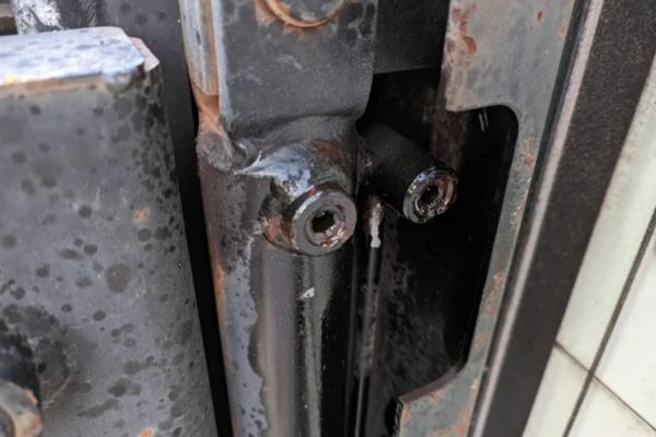
How Do You Isolate Worn Rod Seals from Internal Piston Bypass?
To isolate worn rod seals from internal piston bypass, perform a physical inspection of the exterior gland followed by a pressurized drift test on the hydraulic cylinder barrel. A bad rod seal leaks oil externally during operation, while an internal piston bypass leak allows fluid to slip between high-pressure and low-pressure chambers inside the barrel.
What Are the Visual Red Flags of External Gland Leakage?
External leaks show that the primary barrier against outside air ingress has failed.
- Wet oil rings tracking along the polished rod surface during extension cycles
- Pooling hydraulic oil beneath the front cylinder gland during stationary hold phases
- Heavily packed dirt and grit crusts building up directly on the wiper seal lips
Can a Pressure-Hold Test Confirm Internal Bypass Leakage?
Isolating the fluid chambers helps determine if oil is escaping past the piston seal inside the barrel.
- Isolating the rod-end hydraulic line at full stroke while maintaining system pressure
- Monitoring pressure decay across the piston seal using inline diagnostic gauges
- Measuring volumetric bypass flow from the open rod-end port under maximum working pressure
Confirming whether the leak is internal or external tells you exactly which seals need replacement.
| External Gland Metrics | Piston Seal Internal Leakage | Volumetric Thresholds |
| Dry Rod / No Accumulation | Zero Pressure Drop | Within OEM Tolerance, System Holds Position |
| Wet Film / Minor Puddling | Slow Continuous Pressure Decay | Warning Zone, Internal Seal Degradation Started |
| Active Dripping / Heavy Crust | Immediate Zero-Pressure Drop | Critical Failure, Complete Piston Bypass Occurring |
This comparison clarifies whether you need to rebuild the exterior gland or replace the internal piston seals.
What Is the Exact Step-by-Step Cycle for Bleeding a Hydraulic Cylinder?
The exact cycle for bleeding a hydraulic cylinder involves extending and retracting the rod under low pressure while using a dedicated bleed valve or cracking the highest hose connection point. To ensure long-term reliability, source premium component connections, such as a heavy-duty hydraulic hose fitting, to seal out ambient air after completing the air purge sequence.

How Do You Safely Position the Machine for Low-Pressure Cycling?
Never attempt to bleed air from a system under full working pressure or load.
- Lowering all mobile attachments flat to solid ground to remove mechanical tension
- Fully chocking heavy machinery tires to prevent accidental chassis movement
- Cracking open specialized mechanical bleed screws located at the highest point of the cylinder body
Why Is Lock-to-Lock Cycling Crucial for Purging Trapped Gas?
Moving the piston through its full stroke sweeps out stubborn air pockets trapped in the end caps.
- Running full extension and retraction strokes without heavy mechanical loads attached
- Driving trapped air pockets out of the cylinder end caps and into the return lines
- Forcing aerated fluid back to the reservoir where air bubbles can naturally separate from the oil
Repeating this low-pressure purge sequence ensures that all trapped air is driven out into the reservoir.
| Bleeding Sequence Steps | Pressure Caps | Volumetric Return Targets |
| 1. System Depressurization | 0 PSI Static | Safe Mechanical Neutral Alignment |
| 2. Low-Pressure Extension | Under 500 PSI Working | Initial Gas Sweep to Front Gland Port |
| 3. Lock-to-Lock Cycles | 800 PSI Maximum | Full Displacement, Clear Fluid Return |
Following this structured bleeding sequence removes hidden air pockets without straining your seals.
How Do Reservoir Architecture Failures Drive Continuous Aeration?
Reservoir architecture failures drive continuous aeration because poorly designed or damaged tanks fail to separate returning air bubbles from the oil before it is drawn back into the pump inlet. This creates a continuous cycle where aerated fluid keeps returning to your high-pressure components.
Why Are Internal Baffle Plates Essential for Fluid De-Aeration?
Baffle plates create a physical barrier that gives air bubbles time to rise out of the fluid.
- Forcing returning hot fluid into structured cooling paths along the outer tank walls
- Allowing microscopic air bubbles sufficient dwell time to rise to the oil surface
- Isolating turbulent return flow from the calm oil zone around the pump suction lines
Can a Damaged Reservoir Breather Cap Induce Vacuum Leaks?
The reservoir must breathe freely to maintain stable pressure as fluid levels shift.
- Clogged air filter membranes restricting tank breathing during high-volume extensions
- Pulling structural vacuums inside the tank reservoir during cylinder extension strokes
- Drawing ambient air through weaker mechanical joints and pump shaft packings
Fixing tank design and component defects prevents air from getting drawn back into the high-pressure lines.
| Baffle Geometric Dwell Scales | Breather Flow Capacity | Ambient Isolation Metrics |
| Correct Multi-Baffle Layout | 100% Free Air Exchange | Complete Micro-Bubble Dissipation |
| Straight-Through Tank (No Baffle) | Restricted Air Membrane | Continuous Foam Recirculation to Pump |
| Damaged/Clogged Tank Top | Complete Air Flow Blockage | Structural Vacuum, Air Drawn Past Seals |
This architectural data underscores how vital a healthy reservoir setup is for keeping air out of your fluid.
What Preventive Maintenance Regimen Stops Air Ingress Permanently?
A preventive maintenance regimen stops air ingress permanently by scheduling regular torque checks on suction fittings and conducting routine oil quality tests. This proactive approach catches loose connections and degrading oil before air contamination causes system lag.
How Do Scheduled Torque Inspections Safeguard Suction Line Fittings?
Vibrations from heavy operations can slowly back off threaded fluid connections over time.
- Verifying SAE J1453 O-ring face seal integrity at every major service interval
- Tracking cold-set hose relaxation trends that cause a drop in clamping force
- Inspecting suction line hose clamps for metal fatigue or structural cracking
Should You Deploy Offline Flushing Loops for Seasonal Storage?
Moisture and settled air bubbles can degrade sitting oil during seasonal downtime.
- Deploying absolute kidney-loop micro-filtration setups to clean stagnant oil reservoirs
- Scrubbing water contamination from storage vessels before it alters fluid surface tension
- Pre-filtering new makeup oil blocks to ensure no outside air or dirt enters the machine
Using these defensive maintenance steps stops air ingress from turning into an unexpected equipment breakdown.
| Inspection Interval Targets | Fitting Torque Scales | Fluid Cleanliness Bands |
| Every 250 Operating Hours | Face Seal Hand-Tight + 1/4 Turn | ISO 16/13/11 Clear Fluid Standard |
| Every 500 Operating Hours | Target Flange Specification Bolt Torque | ISO 18/15/12 Moderate Operational Band |
| Every 1000 Operating Hours | Full Line Component Re-Torque | ISO 21/18/15 Action Threshold Required |
Sticking to these inspection intervals ensures your fluid lines stay sealed against outside air.
Conclusion
Managing fluid performance requires tracking mechanical wear, identifying cavitation noise, and maintaining solid component connections. Addressing loose suction joints, inspecting worn rod seals, and keeping reservoirs free of air bubbles prevents erratic component bounce and protects internal metal platings from erosion. If you need reliable performance under tough operating conditions, choosing premium components ensures long-term field uptime. We deliver high-precision, heavy-duty replacement hydraulic cylinders, fittings, and expert engineering support to keep your systems running smoothly. Engineering zero-defect reliability into every high-pressure circuit to secure global industrial uptime. To eliminate field faults today, contact us today.
FAQ
Can I drive a tractor or loader if the cylinder movement feels spongy?
No, operating a machine with aerated fluid accelerates internal cavitation damage and can cause sudden, dangerous load drops. Bleed the circuit immediately before continuing field work.
What’s the best method to find an air leak if no oil is visibly dripping?
Apply a thin layer of heavy mechanical grease around high-risk suction line joints and watch for the grease to be drawn in under vacuum during operation.
How do I know if the foaming problem is caused by air or water contamination?
Run a simple field crackle test by heating an oil sample on a hot plate. Distinct sputtering and popping indicates water contamination, while quiet surface bubbling points to entrained air.
Can a clogged return line filter cause air to be drawn into the cylinder gland?
Yes, excessive backpressure from a clogged filter can damage rod wiper seals during fast retraction strokes, allowing outside air to seep into the cylinder assembly.