
Head Trunnion
Head Trunnion Mount Hydraulic Cylinder
The trunnion pivot is positioned near the rod end, allowing the cylinder body to swing as the machine linkage moves through its operating arc.

TOPA Custom Hydraulic Cylinder Manufacturing
Engineered around your load, stroke and machine geometry. TOPA manufactures head, cap and intermediate trunnion cylinders for OEM equipment, replacement projects and demanding industrial applications.
TOPA supplies different trunnion hydraulic cylinder configurations for OEM equipment, replacement projects and custom machinery. Mounting position, stroke, bore, rod size and connection dimensions can be manufactured according to your application.
The trunnion pivot is positioned near the rod end, allowing the cylinder body to swing as the machine linkage moves through its operating arc.

Designed for tipping and lifting equipment where the cylinder needs to pivot with the body during operation. Dimensions can be matched to replacement or OEM requirements.

A trunnion configuration designed around the rod-side mounting area for machines requiring controlled pivot movement and compact installation geometry.

Combines a serviceable tie-rod cylinder structure with a trunnion pivot mount, suitable for industrial machinery requiring repeatable pivoting motion.
A trunnion mount is designed for mechanisms where the cylinder needs to pivot as the rod end follows an arc. The right mounting geometry helps keep working force close to the cylinder centerline.
The cylinder follows the moving linkage instead of resisting the changing angle through its rod and bearings.
Correctly aligned pivots help transfer push and pull forces without adding unwanted turning moments to the cylinder.
Head, cap and intermediate trunnion positions give designers flexibility when the pivot point is constrained by the machine frame.
The trunnion position determines the cylinder pivot point, installation envelope and movement path. Compare head, cap and intermediate trunnion designs according to your machine structure, available space and linkage geometry.
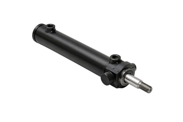 Pivot Near Rod End
The trunnion pivot is positioned near the rod end of the cylinder. This arrangement is suitable when the machine support is located toward the front of the cylinder and the cylinder body needs to swing behind the pivot point.
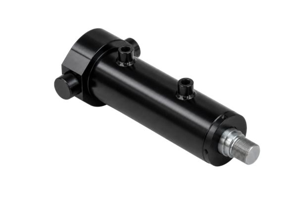 Pivot Near Cap End
The pivot is positioned near the cylinder base or cap end. It is commonly used in lifting, tipping and tilting mechanisms where the rear machine structure provides the main pivot support.
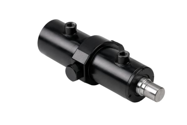 Custom Barrel Pivot
The trunnion is positioned at a selected point along the cylinder barrel. This design gives more flexibility when the machine frame requires a custom pivot center or when installation space must be balanced at both ends.
Pressure is only one part of cylinder reliability. Pivot alignment, bracket rigidity, rod stability and hose movement can determine whether a cylinder runs smoothly or fails early.
The rod-end pivot should remain parallel to the trunnion axis so the cylinder can move without being forced sideways.
The machine load needs its own guidance. The piston rod should not be used as the guide for a moving structure.
Trunnion brackets and bearings need enough rigidity to limit deflection under peak and shock loads.
Full bearing support helps the pins carry their intended shear load instead of introducing harmful bending stress.
Suitable lubrication at the trunnion pins and bearings reduces friction and wear during repeated pivot cycles.
Port direction and hose length must allow full movement without pulling, twisting or repeated tight bending.
The cylinder should be specified as a complete interface with your equipment—not as bore and stroke alone.
| Custom item | Application-based options | Why the buyer should confirm it |
|---|---|---|
| Cylinder action | Double acting or application-specific design | Defines powered movement and the hydraulic circuit. |
| Trunnion position | Head, cap or intermediate | Controls the pivot location and installation envelope. |
| Bore and rod | Selected for force, pressure, stroke and stability | Determines output force and rod buckling margin. |
| Stroke and lengths | Required travel, retracted length and extended length | Prevents overtravel and machine interference. |
| Rod-end connection | Thread, clevis, eye, spherical bearing or custom end | Must pivot correctly with the machine linkage. |
| Ports | BSP, NPT, SAE, metric and specified orientation | Protects access, hose routing and serviceability. |
| Cushioning and sensing | End cushioning and position-sensing options | Supports speed control and machine feedback. |
| Seals and protection | Fluid, temperature, duty-cycle and corrosion options | Matches the actual operating environment. |
Final limits for bore, stroke, pressure, temperature and lead time are confirmed after application review. This avoids publishing a general number that may not be safe for a specific mounting geometry.
Trunnion hydraulic cylinders are commonly used where the cylinder must pivot as the connected machine structure moves through an arc. The mounting position can be adapted to the equipment geometry, available installation space and load direction.

Used in tipping bodies and trailer lifting mechanisms where the cylinder angle changes as the body rises. The pivot mounting allows the cylinder to follow the tipping arc while transferring lifting force through the mechanism.
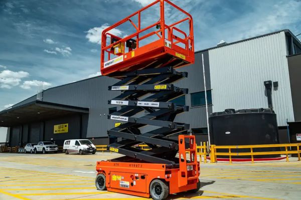
Installed in scissor lifting mechanisms where the cylinder changes angle as the crossed arms open and close. A trunnion mount can provide a compact pivot point while allowing the cylinder to follow the linkage movement.

Used in heavy industrial tilting mechanisms where ladles, tables or handling structures rotate around a fixed pivot. The cylinder must accommodate angular movement while delivering controlled push or pull force.

Used on press tables, forming equipment and other industrial mechanisms where the driven member rotates instead of moving only in a straight line. The trunnion position can be customized to match the machine pivot geometry.
Each component should be selected as part of the load path, sealing system and operating environment.

A controlled internal surface supports seal life and consistent piston movement.
Diameter and surface protection are matched to stroke, load, pressure and environment.
Guides, bearings and seal materials are selected to control friction, wear and leakage.
Pin size, location, welding and dimensional accuracy affect alignment and force transfer.
Port standard and orientation are configured for safe hose movement and service access.
The critical checks follow the buyer's risk: wrong geometry, poor alignment, leakage and dimensions that do not match the approved drawing.

Mounting geometry, load, pressure and operating conditions are checked before production.
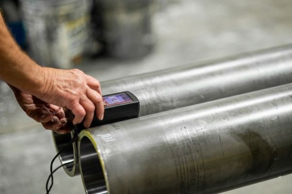
Main materials and purchased components are checked against the approved specification.

Bore, rod, pin and mounting features are controlled through machining.

Pivot location, alignment and welding follow the confirmed drawing.
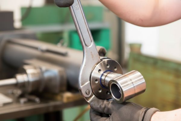
Components are cleaned and assembled to reduce contamination-related problems.
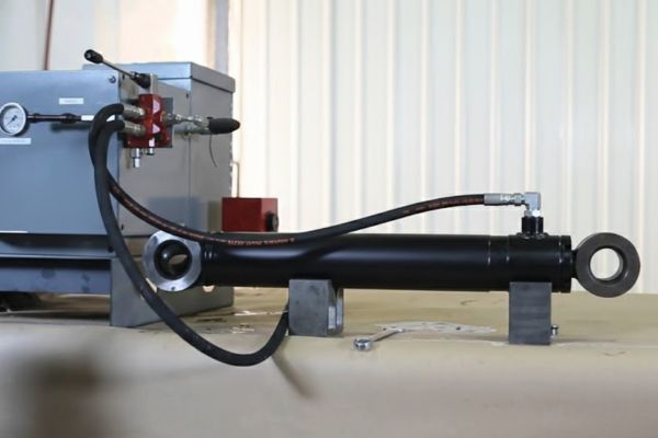
Finished cylinders are checked for pressure retention, movement and external leakage.
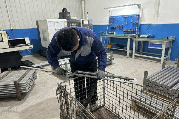
Stroke, lengths, pivot center, pins, width, rod end and ports are verified.

Identification, documentation and export protection are checked before dispatch.
Send the information you can collect. TOPA will organize the critical dimensions and return a drawing for confirmation before production.
Drawing, model, nameplate, photos or available measurements.
Load, pressure, movement and installation conditions.
Bore, rod, stroke, lengths, pins and trunnion location.
Critical interfaces are documented before production.
The approved cylinder is manufactured and inspected.
Protective packaging and shipment information are prepared.
Our value is measured by how clearly we confirm the application, drawings and critical dimensions—not by generic claims.
Mounting and operating information is reviewed before the order enters production.
Both sides confirm the dimensions that determine fit and interchangeability.
Mount, stroke, rod end, ports, seals and protection are adapted to the application.
Pivot location, mounting width, pin diameter and overall length are inspected.
Pressure, leakage and movement checks are completed before shipment.
Suitable for OEM programs, distributors, replacement projects and repeat orders.
Clear answers to the questions that most often affect selection, installation and replacement.
It is a pivot-mounted cylinder with pins located at the head, cap or along the barrel. The mount allows the cylinder to rotate in one plane as the connected mechanism moves through an arc.
The difference is the pivot location. That position changes the installation envelope, hose movement and the distance from the pivot center to each end of the cylinder.
Yes. The position can be designed around the machine geometry, but its center location and related dimensions must be confirmed on a drawing before production.
Review the machine pivot point, motion path, retracted and extended lengths, available space, load direction, pivot angle and hose clearance together.
Common causes include non-parallel pivot axes, flexible brackets, an unguided machine load, movement outside the intended plane and interference during the stroke.
Rod selection considers push load, stroke, mounting arrangement, working pressure, extended length, column stability and the required safety margin.
TOPA can review an original drawing, model number, photos or measured dimensions. A confirmation drawing is used to reduce the risk of an incorrect replacement.
Useful information includes the application, bore, rod, stroke, pressure, mount type, trunnion position, installation dimensions, port details and required quantity.
The inspection plan can include critical dimensions, stroke and movement, pressure retention, external leakage, mounting geometry and final identification.
Yes, after confirming temperature, fluid, corrosion, contamination and duty cycle. Seal materials and surface protection are then selected for the stated conditions.