
Loader Welded Cylinder
Compact welded hydraulic cylinder for loader lifting, tilting and attachment functions where strength, installation space and reliable repeated operation are required.

Explore hydraulic cylinders for loader lifting, bucket control, steering, grapple operation and other working functions. Each cylinder can be reviewed around your machine dimensions, mounting structure and operating requirements.
Compact welded hydraulic cylinder for loader lifting, tilting and attachment functions where strength, installation space and reliable repeated operation are required.

Controls bucket rollback, leveling and dumping movement through the loader linkage, with stroke and mounting dimensions matched to the required bucket travel.

Provides hydraulic movement for the loader boom and bucket linkage, supporting lifting and positioning under changing loads and repeated working cycles.

Drives controlled bucket rotation for loading, positioning and material discharge applications where a wider range of bucket movement is required.

Supports controlled steering movement on wheel loaders by converting hydraulic pressure into precise axle or articulation movement during machine operation.
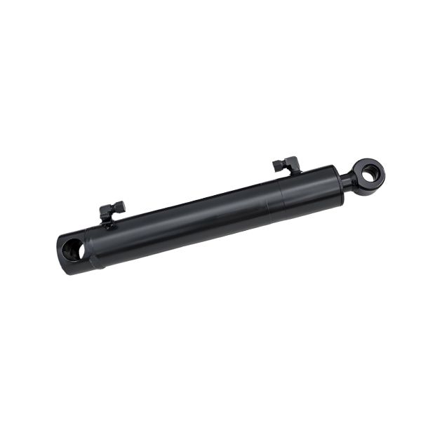
Provides the primary hydraulic force for raising and lowering loader arms, with bore, rod and stroke selected around the required lifting load and geometry.
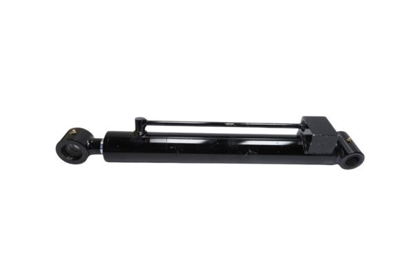
Open and close loader grapple arms for handling timber, hay, brush, scrap and irregular materials with controlled clamping and release movement.
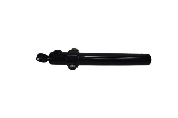
Control front-end loader bucket angle for rollback, carrying, leveling and dumping, with mounting geometry matched to the loader linkage.
The same loader can use several cylinders with different strokes, mounts and force requirements. Confirming the installed position prevents the wrong cylinder from being quoted.
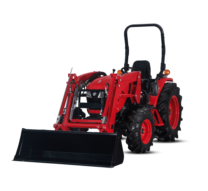
Lift or boom cylinders connect the frame to the loader arm and carry the primary lifting movement.
Tilt cylinders act through the linkage to control rollback, leveling and dumping angle.
Compact cylinders control tool locking or movement on grapples, forks and other attachments.
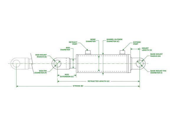
A loader cylinder cannot be selected reliably from outside length alone. These inputs control force, movement, installation fit and hydraulic connection.
| Parameter | Why it matters | What to send |
|---|---|---|
| Bore diameter | Influences available pushing and pulling force. | Drawing value or measured internal bore. |
| Rod diameter | Affects strength, stability and buckling review. | Outside rod diameter and exposed length. |
| Stroke | Controls lift height, steering travel or bucket rotation. | Extended length minus retracted length. |
| Pin-to-pin length | Determines whether the cylinder fits the machine geometry. | Both fully retracted and fully extended lengths. |
| Mounting ends | Must fit the loader frame, linkage and load direction. | Mount type, width, pin diameter and clear photos. |
| Port details | Must match hose thread, orientation and available clearance. | Thread standard, size, position and direction. |
| Working condition | Guides seal, surface, structure and protection choices. | Pressure, temperature, cycle, environment and load. |
Send measurements with clear photos from both sides. TOPA uses the full set to check installation fit before confirming a replacement drawing.
A simple review process helps prevent incorrect stroke, mount, pin and port details from reaching production.
Share machine model, photos, drawing or sample information.
Identify the loader position, movement and operating condition.
Review bore, rod, stroke, mounts, pins, ports and lengths.
Confirm the production drawing and any open technical points.
Move to sample development or agreed production quantity.
Machine size alone does not define the cylinder. TOPA reviews the installed motion, load path, duty cycle and available space for each application.
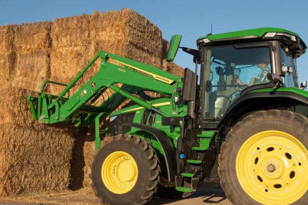
Lift, tilt, grapple and quick-attach cylinders for farm loading, feed, hay and general material handling.
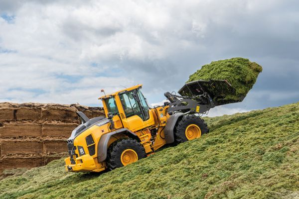
Boom, bucket and steering cylinders for repeated heavy loading, impact and outdoor operation.
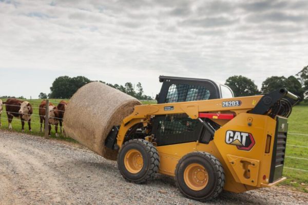
Compact cylinders for lift arms, tilt functions, couplers and multiple attachment systems.
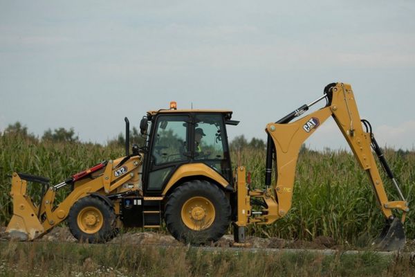
Loader-side lift and bucket functions plus application-specific cylinders for combined equipment.
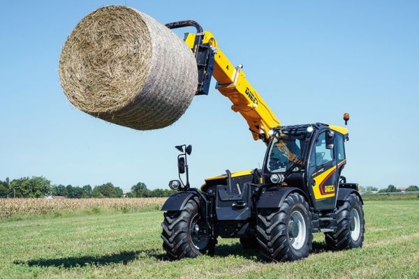
Boom, compensation, steering and attachment cylinders where reach and stability need close review.

Custom cylinders for grabs, clamps, forks, blades and tools exposed to dirt, shock and irregular loads.
“Heavy duty” is not one specification. The right structure and protection depend on how and where the loader works.
TOPA can review these variables from an existing cylinder, an approved drawing or a new equipment requirement.
Match force, return force, stability and installation envelope.
Control full movement without interference or incomplete travel.
Eye, clevis, cross tube, flange or project-specific geometry.
Confirm diameter, width, material and load-transfer details.
Choose thread, size, position and orientation for hose clearance.
Match fluid, temperature, speed, contamination and application.
Review rod finish, coating, paint and corrosion protection.
Support project labels, batch identification and export packing.
Correct dimensions are only the beginning. Loader geometry and working forces also influence rod, mount, seal and connection performance.
Check whether the cylinder follows the linkage path without binding or excessive lateral force.
Review compression load, rod diameter, stroke and unsupported length.
Confirm mounting width, pin fit and load transfer through the machine structure.
Verify hose, port, rod and body clearance at both movement limits.
Match the sealing system to dirt, temperature, fluid and operating cycles.
Close open dimensions and orientations before production begins.
From material preparation to final testing, each cylinder moves through controlled machining, welding, surface treatment, assembly and inspection before shipment.

Steel tubes, piston rods and other components are prepared according to the confirmed drawing, dimensions and production requirements.

Pistons, glands, mounting components and connection details are machined to the dimensions specified in the approved production drawing.
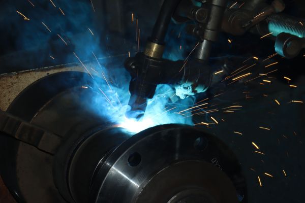
Ports, mounting ends and cylinder structures are welded with attention to alignment, penetration and dimensional consistency.

Rod surfaces, cylinder bodies and exposed components receive the required finishing, coating or painting for the intended working environment.
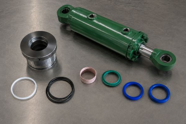
Seals, piston, rod, gland and cylinder components are cleaned, checked and assembled according to the confirmed cylinder specification.
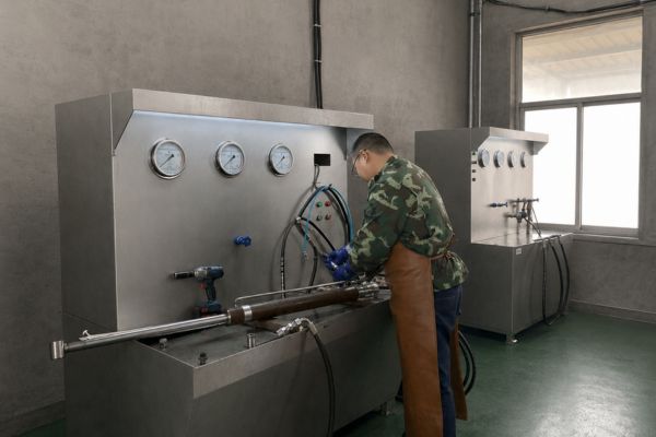
Finished cylinders are checked for dimensions, appearance, operation, pressure performance and leakage before packing and shipment.
A reliable supply program needs controlled machining, assembly, inspection, testing and identification—not only a finished product photo.
Key dimensions are reviewed against the confirmed drawing. Tube, rod, piston, gland, mounts and ports move through machining, welding, assembly and final checks before packing.

Stroke, length, mounts, pins, bore, rod and port details are checked against confirmed requirements.
Rod surface, coating, paint and visible finish are checked before packing.
Testing requirements are confirmed for the application and order specification.
Sealing performance and assembly condition are checked before release.
The supply plan is matched to the buyer type, number of models, technical confirmation and packaging requirements.
Confirm dimensions and function before expanding to larger quantities.
Organize mixed cylinder models around an approved SKU and drawing list.
Use agreed model, batch and private-label information for receiving and reorder accuracy.
Protect rods, ports, painted surfaces and model identification during transport.
Answers to common fitment, replacement, customization and purchasing questions.
Start with the machine brand and model, cylinder installation position and controlled movement. Then provide bore, rod, stroke, retracted and extended pin-to-pin length, mounting dimensions, pin size, port thread and port orientation.
A replacement can often be reviewed from a clear sample, complete measurements and photos. A production drawing should still be confirmed before manufacturing.
Send the complete cylinder from both sides, both mounting ends, hydraulic ports, any product label, the rod surface and the cylinder installed on the loader if possible.
Lift cylinders raise and lower the loader arms. Tilt cylinders act through the bucket linkage to control rollback, leveling and dumping. Their dimensions and force requirements are normally different.
It may be possible when the old cylinder, full dimensions and operating information are available. The matching review must confirm geometry, connections and working conditions.
TOPA reviews port thread, size, distance from reference points, radial direction and hose clearance. Clear photos or a marked drawing help prevent installation conflicts.
Sample feasibility depends on the cylinder design, tooling, materials and project requirements. Include the expected follow-up quantity so TOPA can recommend a practical development path.
Private label, model marking and packaging can be discussed for suitable projects. Send the required label format, packaging standard and order plan for review.
TOPA can help review the key dimensions, mounting points, ports and operating requirements before quotation, so you can avoid costly fitment mistakes.