How to Test a Hydraulic Cylinder Safely with the Right Tools
A sudden loss of hydraulic pressure on an industrial excavator or a heavy-duty agricultural tractor always happens at the worst possible moment, halting operations instantly. You witness fluid weeping past the rod wiper, or worse, the machine arm drifts helplessly under a normal load, delaying project deadlines and spiking field service costs. Diagnosing the exact root cause without damaging the internal components or risking worker safety requires a precise, structured testing protocol. To establish whether your internal seals are bypassing or the structural integrity of the barrel is compromised, you must know how to test a hydraulic cylinder safely using professional diagnostic equipment before ordering custom replacements.
Why Is Pre-Test Visual Inspection Essential Before Hooking Up Gauges?
Directly checking for external deformities, fluid weeping, and scoring on the chrome surface allows you to catch catastrophic failures before applying high-pressure fluid during a live test. Skipping this fundamental mechanical assessment frequently leads to rapid seal destruction or dangerous component bursts under pressure.
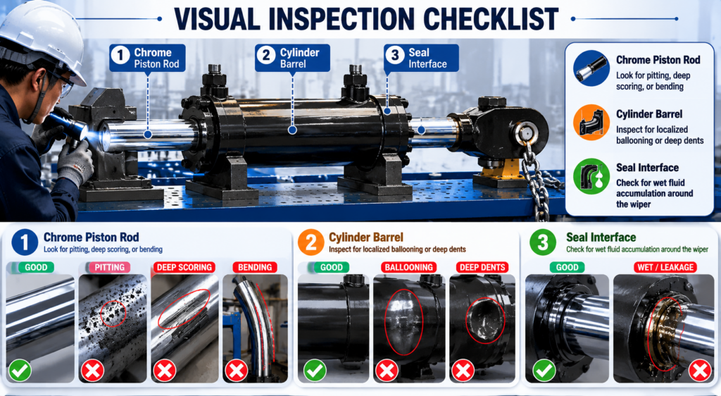
Have you ever noticed fine, parallel lines running down your piston rod?
[Visual Inspection Checklist]
├── Chrome Piston Rod ── Look for pitting, deep scoring, or bending
├── Cylinder Barrel   ── Inspect for localized ballooning or deep dents
└── Seal Interface    ── Check for wet fluid accumulation around the wiper
Deep scoring on the rod surface acts like a saw blade, destroying new seals within hours of installation. Localized ballooning of the outer barrel indicates prior over-pressurization, meaning the internal tolerances are warped beyond repair.
| Inspection Zone | Primary Defect to Find | Immediate Asset Impact |
| Piston Rod Surface | Longitudinal scoring / Pitting | Rapid tearing of polyurethane rod seals |
| Cylinder Barrel Wall | Localized bulging or dents | Internal fluid bypassing the piston seal |
| End Cap / Gland | Hairline fractures in threads | Catastrophic blow-out during pressure tests |
How Can You Safely Vent Trapped Pressure from a Hydraulic System?
You must actuate all control valves through their full ranges of motion with the primary power source completely deactivated to clear fluid energy. Failing to purge this stored energy will result in severe skin-penetration injuries from high-velocity hydraulic fluid when loosening the hose fittings.
- Shut down the primary hydraulic power unit completely.
- Engage the mechanical safety locks or lower all working implements flat to the workshop floor.
- Cycle the manual control levers forward and backward at least six times to bleed downstream accumulators.
- Verify that all system pressure gauges register absolute zero PSI before turning a wrench.
Once the gauges read zero, carefully crack the hose connections using two wrenches to prevent lines from twisting. Always wear heavy leather gloves and a full face shield during this isolation process to guard against unexpected pocket pressures.
| Isolation Step | Tooling Required | Safety Validation Target |
| Power Isolation | Lockout-tagout hardware | Zero motor RPM / Pump rotation ceased |
| Mechanical Grounding | Wooden blocking / Steel jacks | No gravitational potential energy remains |
| Fluid De-energization | Manual valve cycling | Pressure gauge needle drops to 0 PSI/Bar |
Safely purging the residual pressure ensures the hydraulic lines can be uncoupled without any high-velocity fluid spraying into the work area. A completely depressurized system forms the mandatory baseline for safe and accurate diagnostic hookups.
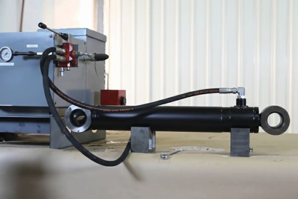
What Equipment Is Required to Perform an Accurate Bypass Test?
Gathering calibrated high-pressure digital gauges, rated isolation needle valves, a portable hydraulic hand pump, and transparent observation hoses ensures precise monitoring. Utilizing substandard or unrated plumbing fittings will compromise your diagnostic accuracy and create severe safety hazards.
- Two digital pressure gauges rated to at least 10,000 PSI to capture sudden pressure spikes.
- High-pressure needle isolation valves designed for bidirectional fluid blocking.
- Heavy-duty rated hydraulic hoses equipped with quick-disconnect test couplings.
- A transparent, wire-reinforced return line to visually observe bypassing oil bubbles.
Using unrated components or low-pressure hoses during a bypass evaluation invites catastrophic mechanical bursts. Calibrated diagnostic instruments give you the exact metrics needed to determine if an internal fluid bypass is occurring.
| Required Diagnostic Tool | Minimum Specification | Explicit Analytical Role |
| Digital Test Gauges | 0–10,000 PSI (±0.25% accuracy) | Measures precise pressure decay over time |
| Needle Isolation Valves | 6,000 PSI working pressure | Blocks fluid return lines to isolate internal paths |
| Transparent Return Hose | 500 PSI rated (suction side) | Permits visual confirmation of internal seal bypass |
Having the correct, high-pressure rated diagnostic array ensures your testing yields definitive data without endangering your service personnel. Once your diagnostic array is connected, you can confidently begin isolating internal component wear.
How Do You Set Up the Bench for a Cylinder Mid-Stroke Test?
Securing the assembly into a heavy-duty welding fixture or specialized repair bench prevents unexpected longitudinal twisting or dangerous bucking during high-pressure cycles. An unanchored component can shift with thousands of pounds of force, causing severe injury or destroying surrounding workshop equipment.
Consider the immense forces generated by even a modest three-inch bore industrial cylinder.
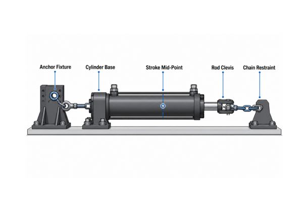
[Bench Setup Configuration]
[Anchor Fixture] ── [Cylinder Base] ══ [Stroke Mid-Point] ══ [Rod Clevis] ── [Chain Restraint]
At 3,000 PSI, that unit exerts over 21,000 pounds of linear force, easily throwing unsecured components across your workshop floor. Install heavy steel pins through both the base clevis and the rod eye, securing them tightly to the steel bench frame.
- Position the cylinder precisely at the exact midpoint of its total stroke length.
- Drive hardened steel pins through the mounting eyes to anchor the assembly to the bench.
- Wrap heavy-duty transport chains over the center barrel as a secondary deflection guard.
- Clear all non-essential personnel from the linear path of the extending rod.
Anchoring the unit firmly ensures that any unexpected pressure spikes or mechanical releases are safely contained by the steel framework of the repair bench. With the component safely restrained, you can proceed to evaluate the integrity of the internal piston seals.
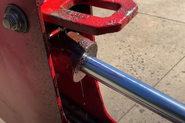
What Are the Precise Steps for Conducting a Piston Bypass Test?
Pressurize the cap end of the hydraulic cylinder to its maximum rated operating limit while leaving the rod-end port open to observe any oil leaking past the piston seals. Internal oil bypass confirms that the T-seals or piston rings are worn, allowing oil to escape into the return system.
This test is the most definitive way to check for internal structural wear.
- Connect your high-pressure supply line directly to the cap-end port of the cylinder.
- Attach a transparent observation line to the open rod-end port, routing it into a clean container.
- Slowly supply hydraulic fluid until the unit reaches its full rated operating pressure.
- Monitor the open transparent line for continuous fluid flow for at least three minutes.
A few initial drops of oil are normal as the internal air purges, but a steady stream of fluid proves that the piston seals are severely worn.
| Test Phase | Port Configuration | Observable Indicator of Failure |
| Pressurization | Cap-end pressurized to 3,000+ PSI | Rapid pressure drop on the primary digital gauge |
| Observation | Rod-end port left open to air | Continuous oil stream exiting the transparent line |
| Stabilization | Needle valve closed for 3 minutes | Gauge pressure drops more than 100 PSI per minute |
Documenting the exact volume of oil bypassing the internal piston provides a clear metric of your seal wear. Catching internal bypass early prevents system-wide overheating and protects downstream hydraulic pumps from contamination.
How Does a Drift Test Differ from a Live Hydraulic Bypass Test?
A drift test measures the physical retraction or extension of the piston rod over an extended period with the control valves locked, rather than measuring active fluid bypass. This test helps determine if the positioning drift is caused by internal cylinder wear or a leaking control valve spool.
You must differentiate between mechanical movement and active fluid loss to avoid misdiagnosing the issue.
[Drift Testing Breakdown]
├── Internal Cylinder Failure ── Oil leaks across piston seals (Rod drifts down)
└── Control Valve Failure     ── Oil leaks past spool back to tank (Rod drifts down)
Mechanical drift can be caused by fluid leaking past the internal piston seals or by high-pressure oil weeping past a worn control valve spool back to the oil reservoir. To isolate the cylinder, you must lock the fluid inside the barrel chambers using high-pressure needle valves, completely bypassing the main control valve.
- Extend the piston rod under a normal operational load to its mid-stroke position.
- Close the inline needle isolation valves tightly to trap the fluid within both cylinder chambers.
- Shut off the primary hydraulic pump to eliminate all external system pressure influences.
- Mount a dial indicator gauge against the rod shoulder and record the linear position over 30 minutes.
If the rod still moves with the needle valves tightly closed, the oil is bypassing the internal piston seals. If the movement stops completely when isolated, your positioning drift is caused by a leaking control valve spool upstream.
| Test Type | Metric Monitored | Primary Component Isolated |
| Active Bypass Test | Volumetric fluid flow (mL/min) | Piston seal and internal barrel wall finish |
| Static Drift Test | Linear rod displacement (mm/hour) | Combined circuit integrity (Valve spool vs. Cylinder) |
Isolating the cylinder from the control valve prevents you from replacing healthy components based on a misdiagnosis. Accurate drift profiling ensures your maintenance resources are focused on the true root cause of the system failure.
How Do You Interlock High-Pressure Gauges for a Pressure Decay Test?
Connect digital pressure gauges to both the cap and rod ends, pressurize the system, and close the isolation valves to monitor the rate of pressure loss over time. A rapid drop in pressure indicates an internal leak or an external fracture in the cylinder structure.
This method allows you to catch minor internal leaks before they cause complete mechanical failure.
- Install high-precision digital gauges into the diagnostic ports on both ends of the cylinder.
- Pressurize the cap-end chamber to the full factory-specified test pressure.
- Close the inline isolation valves to seal the oil inside the cylinder barrel.
- Record the pressure readings on both gauges every 60 seconds for a 10-minute testing window.
A healthy cylinder will maintain its pressure with minimal drop, losing less than 50 PSI over the entire 10-minute window. A sharp drop on one gauge accompanied by a rise on the other confirms that oil is bypassing the internal piston seal.
| Time Interval | Cap-End Pressure (PSI) | Rod-End Pressure (PSI) | Diagnostic Evaluation |
| 0 Minutes | 3,000 PSI | 0 PSI | Baseline setting; isolation valves closed |
| 5 Minutes | 2,750 PSI | 240 PSI | Active internal bypass; fluid moving across piston |
| 10 Minutes | 2,400 PSI | 580 PSI | Severe internal seal failure confirmed |
Analyzing this pressure data prevents guesswork, letting you know exactly when an internal seal or barrel wall is worn out. Tracking pressure decay over time gives you a clear picture of the internal condition of your hydraulic assets.
What Specific Indicators Confirm Internal Cushioning Valve Failures?
A loud metallic banging at the end of the stroke or irregular deceleration indicates that the internal cushioning spears or adjustment needles are worn. Worn or damaged cushioning components fail to slow the heavy piston down, leading to structural damage over time.
Have you noticed your machinery shaking violently as the cylinder reaches the end of its stroke?
- Listen for a loud metallic clanging sound at the end of the cylinder’s stroke.
- Check the adjustable cushion needle screws for external fluid leaks or damaged threads.
- Monitor the cylinder’s deceleration profile as it approaches its physical travel limit.
- Inspect the hydraulic return lines for fine metallic shavings during the cushioning phase.
When cushioning valves fail, the piston impacts the end caps at full speed, creating high structural stresses that can crack the housing. Inspecting and replacing worn cushioning components prevents catastrophic structural failures.
| Cushioning Symptom | Root Mechanical Cause | Long-Term Component Risk |
| End-of-stroke metallic impact | Cushion spear ring or check valve stuck open | Cracked cylinder end caps / Bent mounting pins |
| Irregular or jerky deceleration | Scored cushion needle valve seat | Internal pressure spikes tearing rod seals |
Identifying cushioning failures early protects your heavy equipment from destructive high-impact forces. Keeping these specialized internal valves properly maintained extends the working life of the entire cylinder assembly.
How Do You Safely Recommission a Cylinder After Completing Pressure Tests?
Slowly open the isolation valves and cycle the cylinder through its full stroke multiple times under zero load to purge trapped air from the system. Trapped air causes dangerous cylinder sponginess, irregular movement, and seal damage from localized diesel effect explosions.
Properly purging air from the lines is critical for safe operation.
- Slowly open all inline needle isolation valves to reconnect the cylinder to the main system.
- Start the main hydraulic pump and run it at its lowest idle speed setting.
- Cycle the piston rod back and forth through its full stroke at least ten times without any mechanical load.
- Crack the integrated air bleed screws at the ends of the stroke until bubble-free fluid flows out.
Leaving air trapped inside the cylinder barrel causes jerky, erratic movement and can ruin new seals through high-temperature air compression. Thoroughly purging the air ensures smooth operation and long-term reliability.
| Recommissioning Step | Operational Target | System Validation Metric |
| Air Purging | Low-pressure cycling | Eliminates erratic movement and pump cavitation |
| Leak Verification | Full system operational pressure | Zero fluid wetting at rod gland and port welds |
| Torque Inspection | Re-tightening mounting hardware | Mounting bolts checked with a calibrated torque wrench |
Maintaining thorough testing records ensures that every cylinder returned to the field meets OEM safety and performance standards. If your current components fail to meet these rigorous standards during testing, contact us today to procure heavy-duty, factory-certified hydraulic cylinders built to withstand your toughest industrial challenges.
FAQ
Can I test a hydraulic cylinder without a hydraulic hand pump?
No, you cannot safely or accurately test internal cylinder integrity without a regulated hydraulic pressure source. Attempting to test a cylinder using mechanical force or unmetered air pressure is dangerous and cannot generate the high fluid pressures needed to verify internal seal integrity.
What is the best way to verify that a rod is not bent?
The most reliable method is to place the removed piston rod onto precision V-blocks and measure it with a dial indicator along its entire length. If the rod shows a total indicator reading variation of more than 0.002 inches per foot of length, it is bent beyond acceptable limits and must be replaced.
How do I know if my cylinder problem is actually an internal leak?
If the cylinder drifts under load but stops moving when isolated by manual needle valves, the problem is an upstream control valve issue rather than an internal leak. If the rod continues to drift even when the needle valves are closed tightly, the fluid is bypassing the internal piston seals.
Can I change cylinder seals while the unit is still mounted on the machine?
Yes, you can replace the rod gland seals on many light-duty systems without removing the entire cylinder from the machine, provided the workspace is completely clean. However, for heavy-duty or large-bore industrial components, the unit should be brought to a dedicated repair bench to prevent contamination and ensure proper torque specs.
How often should industrial hydraulic cylinders undergo pressure testing?
Cylinders working in high-intensity applications like mining or heavy construction should undergo a formal pressure test every 12 months or every 2,000 operating hours. Implementing this regular testing schedule helps catch minor internal wear before it turns into an expensive field failure.