How Hydraulic Cylinders Are Made: Material Guide
You are running a demanding fleet of agricultural or construction equipment, and suddenly a major loader boom drops mid-operation, or a heavy steering cylinder fails right in the middle of harvest season. The immediate consequence is catastrophic downtime, skyrocketing repair bills, and missed operational deadlines. When field performance collapses, the true vulnerability usually traces back to an unverified manufacturing shortcut or a subpar metallurgical selection made months ago at the factory level.
What Raw Material Criteria Prevent Structural Barrel Failures?
Seamless cold-drawn carbon steel tubing serves as the structural foundation for heavy-duty hydraulic cylinder barrels. Industrial applications demand materials that exhibit high yield strength and flawless internal uniform composition to withstand continuous high-pressure spikes without permanent radial deformation.

[Raw Seamless Steel Tube] ➔ [Skiving & Roller Burnishing] ➔ [Honed ID Wall (<0.4µm Ra)]
Why Select ASTM A513 Type 5 Steel?
Dominating heavy-duty manufacturing, ASTM A513 Type 5 DOM (Drawn Over Mandrel) steel provides superior dimensional accuracy and concentricity compared to traditional hot-rolled alternatives. For extreme-impacting heavy environments, choosing carbon steel variants like ST52.3 or E355 offers enhanced tensile strength thresholds up to 600 MPa.
- Microstructure Stability: The DOM stretching process realigns molecular grain structures parallel to the stress axis.
- Pressure Retention: High yield limits allow thinner, lighter walls to safely contain working pressures exceeding 3,000 PSI.
- Machining Margin: Uniform material density eliminates localized hard spots during internal boring processes.
How Does Skiving and Roller Burnishing Enhance ID Quality?
Skiving and roller burnishing represents the premier internal diameter (ID) finishing workflow, replacing old, slower multi-pass honing techniques. Skiving blades quickly cut raw internal stock to tight dimensional limits before hardened rollers mechanically compress the surface peaks, creating an ultra-smooth profile.
- Roughness Reduction: Achieves an internal finish below 0.4 µm Ra, drastically minimizing frictional drag on dynamic seals.
- Surface Hardening: Burnishing induces localized compressive stresses, increasing surface hardness by up to 30%.
- Geometry Correction: Rectifies minor ovality faults to secure an absolute concentric cylinder bore line.
What Machining Standards Eliminate Cylinder Rod Pitting?
The hydraulic piston rod is the primary component exposed directly to external environmental debris, requiring strict precision machining to prevent fluid bypass and seal degradation. Minor surface imperfections act as cutting edges that destroy polyurethane wipers during high-speed retraction cycles.
Why Choose Medium Carbon Steel for Rod Cores?
Utilizing precision-ground AISI 1045 or high-yield AISI 4140 carbon steel bars provides the necessary core toughness to resist heavy bending moments caused by structural deflection or accidental side loading.
- Tensile Core Strength: AISI 1045 delivers a reliable base yield strength of 530 MPa, while alloyed 4140 exceeds 650 MPa.
- Fatigue Resistance: Medium-carbon compositions absorb high-frequency load variations without propagating hairline fractures.
- Induction Adaptability: The material responds perfectly to localized heat treatment without altering core ductility properties.
What Structural Benefit Does Induction Hardening Provide?
Induction hardening passes the raw steel bar through high-frequency electromagnetic fields followed by a rapid liquid quench, transforming the outer perimeter into a rigid martensitic structure while keeping the core flexible.
- Hardness Depth: Produces a protective shell measuring 50 to 55 HRC at an engineered depth of 1.5mm to 3.0mm.
- Impact Protection: Prevents surface denting from flying gravel, dropped tools, or coarse agricultural debris.
- Seal Shielding: Stops micro-dents from forming raised metal burrs that tear secondary rod seal lips.
| Material Grade | Base Yield Strength | Surface Hardness Range | Optimal Application Use-Case |
|---|---|---|---|
| AISI 1045 | 530 MPa | 50–55 HRC (Hardened) | Standard Utility & Light Loader Rams |
| AISI 4140 | 650 MPa | 54–60 HRC (Hardened) | Heavy Excavator Booms & High Shock Links |
How Does Hard Chrome Plating Prevent Fluid Leakage?
Hard electro-chemical chrome plating is the industry-standard method for isolating raw medium-carbon steel rods from corrosive atmospheric moisture and abrasive chemicals. This defensive chemical process determines the ultimate operational lifespan of external components.
What Coating Parameters Prevent Plating Delamination?
Maintaining an optimal plating thickness between 25 and 50 microns per side ensures a robust barrier without inducing structural brittleness that causes micro-cracking under high pressure.
- Micro-Cracking Density: Controlled micro-crack distribution retains lubricating oil films without creating open paths to base steel.
- Adhesion Integrity: Precise chemical bath balancing eliminates micro-voids, stopping early flaking under high stress.
- Hardness Optimization: Deposits a surface layer reaching 850 to 1000 HV, resisting scratching from high-velocity dust.
Why Evaluate Salt Spray Performance Metrics?
Exposing finished plated rods to neutral salt spray testing under ASTM B117 protocols provides an empirical measure of real-world environmental survival. High-tier industrial cylinders must meet a minimum requirement of 96 to 120 hours at a rating of 9 or higher.
- Chemical Insulation: Blocks aggressive fertilizers, manure acids, and salt-laden coastal atmospheres from attacking the rod steel.
- Pitting Defense: Prevents microscopic localized rust cells from forming beneath the active chrome plating layer.
- Seal Longevity: Maintains a smooth, non-porous interface that preserves flexible seal compound integrity.
What Welding Protocols Guarantee Zero-Defect End Cap Junctions?
Joining the heavy rear end cap or mounting clevis to the processed seamless steel barrel creates a joint subjected to extreme tensile and compressive loading. Any structural voids or impurities inside this critical weld profile invite sudden catastrophic joint separation.
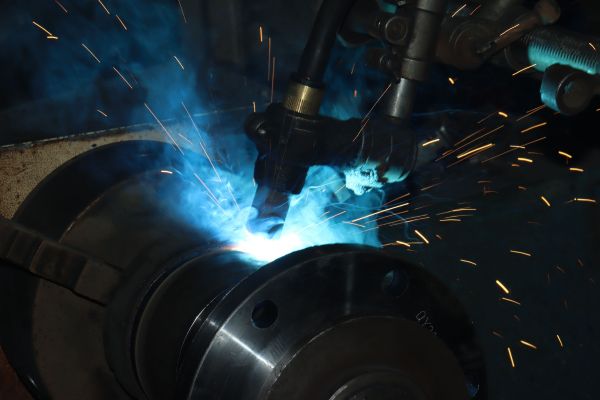
[Barrel Wall & Base Cap] ➔ [Precise J-Groove Prep] ➔ [Friction / Robotic MIG Weld]
Why Prefer Robotic MIG and Friction Welding?
Automated robotic Metal Inert Gas (MIG) welding and advanced continuous-drive friction welding eliminate human variability, delivering deep, absolute weld penetration across the entire cross-sectional area of the barrel junction.
- Heat Input Control: Robotic parameters precisely modulate amperage to limit heat-affected zone (HAZ) grain growth.
- Molecular Bonding: Friction welding physically spins components together under immense pressure, forging a solid-state joint.
- Porosity Elimination: Shielding gas delivery systems exclude atmospheric oxygen, stopping internal bubble formulation.
How Do Multi-Pass Welds Prevent Fatigue Fractures?
Thick-walled industrial barrels require structured multi-pass welding techniques to fill deep structural bevels without inducing excessive residual thermal contraction strains.
- Root Penetration Safety: The initial pass establishes a continuous base weld bead free of root-edge gaps.
- Layer Stress Relief: Subsequent weld passes anneal previous deposits, refining grain sizes across the joint interface.
- Defect Screening: Non-destructive ultrasonic scanning reveals hidden slag inclusions before the component moves to assembly.
| Joint Configuration | Welding Methodology | Typical Penetration Depth | Quality Validation Protocol |
|---|---|---|---|
| J-Groove Barrel Base | Multi-Pass Robotic MIG | 100% Core Depth | Ultrasonic Volumetric NDT |
| Solid Mount Clevis | Solid-State Friction | Continuous Interface | Automated Flash Machining Check |
Which Gland and Piston Machining Fits Stop Pressure Bypass?
The internal piston head and the external head gland guide assembly control the linear tracking of the rod through the barrel bore. Any dimensional deviations in these iron components allow geometric misalignment, leading to metal-to-metal contact and seal failure.
Why Use Ductile Iron for Internal Guide Components?
Specifying high-grade ductile iron, such as GGG50 or Class 65-45-12, provides self-lubricating graphite structures that prevent metal galling during sudden lateral load changes.
- Wear Buffering: The graphite micro-spheres absorb light mechanical contact without scratching polished bore walls.
- Machining Uniformity: Enables high-precision lathe turnings to secure absolute perpendicularity across seal grooves.
- Deformation Resistance: Yield strengths exceeding 400 MPa prevent groove distortion during extreme pressure shifts.
How Do Concentric Tolerances Prevent Piston Side-Loading?
Machining internal piston diameters and external rod paths to concentricity tolerances under 0.03mm stops localized offset tracking.
- Equalized Clearance: Ensures the flexible wear rings share side-loading forces evenly across the cylinder circumference.
- Seal Extrusive Defense: Minimizes the dangerous clearance gap on the low-pressure side of the piston head.
- Frictional Equilibrium: Maintains uniform tracking speed throughout the entire stroke length of the cylinder.
What Seal Configurations Survive Continuous High-Pressure Cycling?
Modern heavy machinery places intense thermal and structural demands on flexible fluid-sealing networks. A single compound breakdown inside the piston assembly immediately results in internal pressure bypass, causing the machine boom to slowly drift out of position.
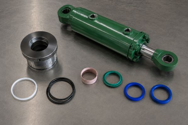
Why Combine Polyurethane and PTFE Seal Elements?
Using premium polyurethane (PU) for defensive outer lips alongside specialized polytetrafluoroethylene (PTFE) for dynamic inner rings ensures friction-free sealing performance across extensive thermal windows.
- Abrasion Endurance: High-grade PU compounds withstand continuous scraping actions against burnished barrel walls.
- Extrusion Defiance: Rigid nitrile elastomers act as anti-extrusion back-up rings during high-pressure spikes.
- Low Breakout Friction: Modified PTFE faces eliminate jerky slip-stick movements during fine positioning adjustments.
How Do Dual-Lip Rod Wipers Defend Internals?
The rod wiper is the first line of defense against incoming track contamination, wiping away microscopic fine dust and liquid mud before it accesses primary internal chambers.
- Primary Mud Scraping: An aggressive external scraping lip removes baked-on heavy soil and field ice.
- Secondary Oil Containment: A flexible internal seal lip prevents residual oil micro-films from traveling past the gland.
- Contamination Blocking: Stops fine silica particles from embedding into wear rings and scoring polished metal tracks.
| Functional Position | Component Structure | Primary Compound Material | Dynamic Pressure Limit |
|---|---|---|---|
| Main Piston Face | Step-Seal with O-Ring Energizer | Virgin PTFE / NBR 70 Shore | 5,000 PSI |
| Gland Rod Channel | U-Cup Profile with Backup Ring | Premium Polyurethane 92 Shore | 3,600 PSI |
How Does Non-Destructive Testing Verify Cylinder Load Safety?
Before any completed hydraulic actuator leaves the production floor, it must undergo strict quality inspections. Non-destructive testing (NDT) confirms that each welded joint and machined component can safely handle its rated field capacity.
Why Implement 100% Volumetric Ultrasonic Inspections?
Ultrasonic testing (UT) utilizes high-frequency acoustic wave reflections to look deep inside solid metal joints, exposing subsurface defects without altering the finished hydraulic cylinder structure.
- Internal Defect Detection: Reveals deep welding micro-voids, root slag inclusions, and lack-of-fusion zones.
- Wall Thickness Tracking: Validates uniform barrel thickness around the circumference after machining.
- Structural Assurance: Guarantees weld strength matches or exceeds parent metal yield limits.
What Flaw Thresholds Demand Immediate Component Rejection?
Establishing absolute inspection limits prevents components with structural flaws from reaching active machine lines.
- Crack Tolerance: Zero tolerance for linear indications or surface-breaking hairline fractures.
- Porosity Restrictions: Any isolated internal voids exceeding 1.5mm require automated assembly sorting.
- Acceptance Mapping: All certified components receive a permanently stamped tracking matrix code for full lifecycle history.
What Anti-Corrosion Finishes Survive Harsh Field Exposure?
The final manufacturing step applies an external protective coating to prevent environmental corrosion from attacking the structural steel barrel. Unprotected metal frames exposed to outdoor weather quickly develop surface rust that weakens ports and mounting pins.

Why Specify Multi-Component Polyurethane Painting?
Industrial multi-stage polyurethane coating systems provide chemical resistance and impact durability that far exceeds standard aerosol primer paints.
- Chemical Defense: Resists degradation from diesel fuel leaks, hydraulic oils, and acidic cleaning chemicals.
- Chipping Resistance: Flexible resin chains absorb impacts from loose gravel without cracking the paint seal.
- Moisture Blocking: Forms an impermeable shell that prevents rust formation on raw exterior surfaces.
How Does Proper Shot-Blasting Maximize Primer Adhesion?
Applying premium paint over raw steel with mill scale guarantees premature coating failure. Automated shot-blasting provides the optimal surface preparation.
- Scale Elimination: Steel shot grit removes all oxidation and manufacturing slag from outer walls.
- Anchor Profile Engineering: Creates a controlled 40-micron profile that mechanically anchors the primer layer.
- Longevity Extension: Proper pre-treatment increases overall paint adhesion life by up to 300% in humid field conditions.
Frequently Asked Questions
Can I rebuild a cylinder with scored inner barrel walls?
No, deep internal wall scoring exceeding 0.2mm generally requires replacing the seamless steel barrel entirely. Installing new polyurethane seal groups over a scratched internal diameter results in rapid seal tearing and immediate pressure bypass under load.
What’s the best way to verify if a rod is bent without removal?
Extend the hydraulic ram to exactly 50% of its stroke length and place a precision machinist’s straightedge along the polished chrome surface. Rotate the rod assembly manually; any changing gap between the straightedge and the chrome highlights a bent rod that requires shop replacement.
How do I know if an internal piston seal is leaking?
Operate the machine until the system reaches its standard warm operating temperature, then drive the cylinder to its absolute mechanical stroke limit. Safely disconnect the return-line hydraulic hose at the opposite port and apply full pressure; continuous oil flow from the open port confirms internal fluid bypass.
Can a pitted cylinder rod be sanded down for temporary use?
Yes, minor surface pitting can be carefully polished using 600-grit emery cloth to remove raised metal burrs that threaten incoming wiper seals. However, this method removes the protective hard chrome plating layer, exposing the raw carbon steel underneath to rapid environmental corrosion.
How do I identify if my cylinder uses tie-rod or welded architecture?
Tie-rod configurations utilize long exterior structural steel bolts running length-wise to hold end caps against the barrel walls, making them ideal for lower-vibration industrial machinery. Welded designs fuse heavy end mounts directly to the seamless barrel body, providing a more compact, high-strength footprint suited for heavy outdoor equipment.