How Does a One Way Hydraulic Cylinder Work in Your Application?
A one way hydraulic cylinder works by utilizing pressurized fluid to generate force in a single direction, typically for extending a piston rod, while relying on an external force such as gravity or an internal spring to retract it. You often face the frustration of inconsistent lifting speeds or sudden pressure drops that halt your production line. These mechanical inefficiencies agitate your bottom line, leading to expensive downtime and missed delivery deadlines. Understanding how does a one way hydraulic cylinder work allows you to select the most efficient, cost-effective actuator for your specific industrial application.
What Is the Basic Principle of a One Way Cylinder?

The core principle of a one way cylinder involves hydraulic oil entering a single port to apply pressure against the base of a piston. This action creates linear motion in one direction, usually the “extension” stroke, to move a heavy load.
When you examine how a one way hydraulic cylinder operates, you will notice it lacks the complex secondary plumbing of double-acting models. Because there is only one fluid path, your system remains simpler and significantly easier to troubleshoot during routine inspections.
The Single-Port Advantage
A single-acting cylinder features only one opening where hydraulic fluid can enter or exit the chamber. When your pump activates, oil is forced into this port, building the necessary pressure to overcome the resistance of your load.
Think about it.
- Reduced risk of fluid cross-contamination.
- Lower complexity in hydraulic hose routing.
- Simplified control valve configurations.
- Fewer potential leak points at the cylinder head.
Directional Force and Fluid Return
The hydraulic pump only does work during the extension phase, making the process highly energy-efficient for vertical applications. Once the pressure is released, the fluid must travel back through the same port it entered, driven by the weight of the equipment.
| Component | Function | Advantage | |
|---|---|---|---|
| Single Port | Entry/Exit for oil | Simplifies plumbing | |
| Piston Face | Receives fluid pressure | Maximizes lift force | |
| Seal Kit | Prevents internal bypass | Enhances efficiency |
This streamlined design ensures that your mechanical energy is focused entirely on the primary task without wasting power on a return stroke that gravity can handle for free.
By minimizing the number of moving parts and fluid paths, you create a more reliable system that thrives in rugged environments.
Why Choose a Single Acting Design for Heavy Lifting?
You should choose a single-acting design when your application requires massive force in one direction and utilizes natural forces for the return cycle. These units are the industry standard for stable, high-capacity vertical lifting where precision and safety are paramount.
Selecting the right actuator is essential for how to choose hydraulic cylinder types for stable control in heavy-duty environments. This specific configuration allows you to maximize your lifting capacity while minimizing the overall size and weight of your hydraulic hardware.
Maximizing Vertical Efficiency
In a vertical lift scenario, the weight of the load itself serves as a free energy source for the retraction phase. This eliminates the need for a secondary pressurized line, which saves you both money on components and space in your machine housing.
It’s a game-changer.
- Drastically reduces hydraulic oil volume requirements.
- Simplifies the integration of safety velocity fuses.
- Lowers the heat generation within your hydraulic reservoir.
- Provides a “fail-safe” descent if pump power is lost.
Cost-Effectiveness and Durability
Because these cylinders have fewer internal seals and no secondary chamber, they are generally less expensive to manufacture and maintain. You get a robust tool that can withstand the vibrations of a construction site or the repetitive cycles of an industrial press.
| Feature | Single Acting | Impact | |
|---|---|---|---|
| Internal Seals | Minimal | Lower friction loss | |
| Valve Setup | 3-way valve | Reduced system cost | |
| Energy Use | Unidirectional | Lower operational power |
The inherent simplicity of this design makes it the most logical choice for any application where the return stroke is assisted by external forces.
Choosing a single-acting unit allows you to allocate your budget toward higher-quality chrome rods and premium seals rather than redundant plumbing.
How Does Fluid Pressure Drive the Extension Stroke?
Fluid pressure drives the extension stroke by filling the cylinder barrel and pushing against the piston’s surface area to convert hydraulic energy into mechanical force. As the pump sends oil into the pressure chamber, the volume increases, forcing the rod to move outward.
The extension phase is the most critical part of how a one way hydraulic cylinder functions under load. By controlling the flow rate of the incoming oil, you can manage exactly how fast your equipment rises or extends.
The Mechanics of Linear Motion
The extension speed is a direct result of the pump’s displacement divided by the piston’s surface area. This relationship gives you predictable, steady motion that is vital for tasks like positioning steel beams or tilting a dump bed.
But that’s not all.
- Pressure builds only when resistance is met.
- Force is evenly distributed across the piston face.
- Motion remains smooth through the entire stroke length.
- Internal stops prevent over-extension damage.
Pascal’s Law in the Cylinder
Hydraulic systems operate on the principle that pressure applied to a confined fluid is transmitted undiminished in every direction. In your cylinder, this means the pump pressure is applied directly to the piston, creating the massive tonnage required for industrial work.
| Variable | Role in Extension | Control Method | |
|---|---|---|---|
| System PSI | Determines total tonnage | Relief valve setting | |
| GPM Flow | Determines extension speed | Flow control valve | |
| Oil Viscosity | Affects response time | Thermal management |
Properly managing these fluid dynamics ensures that your extension stroke is both powerful enough for the task and precise enough for safety.
Consistency in your fluid pressure translates directly into the reliability of your mechanical output during the most demanding phases of operation.
What Role Does Gravity Play in Piston Retraction?
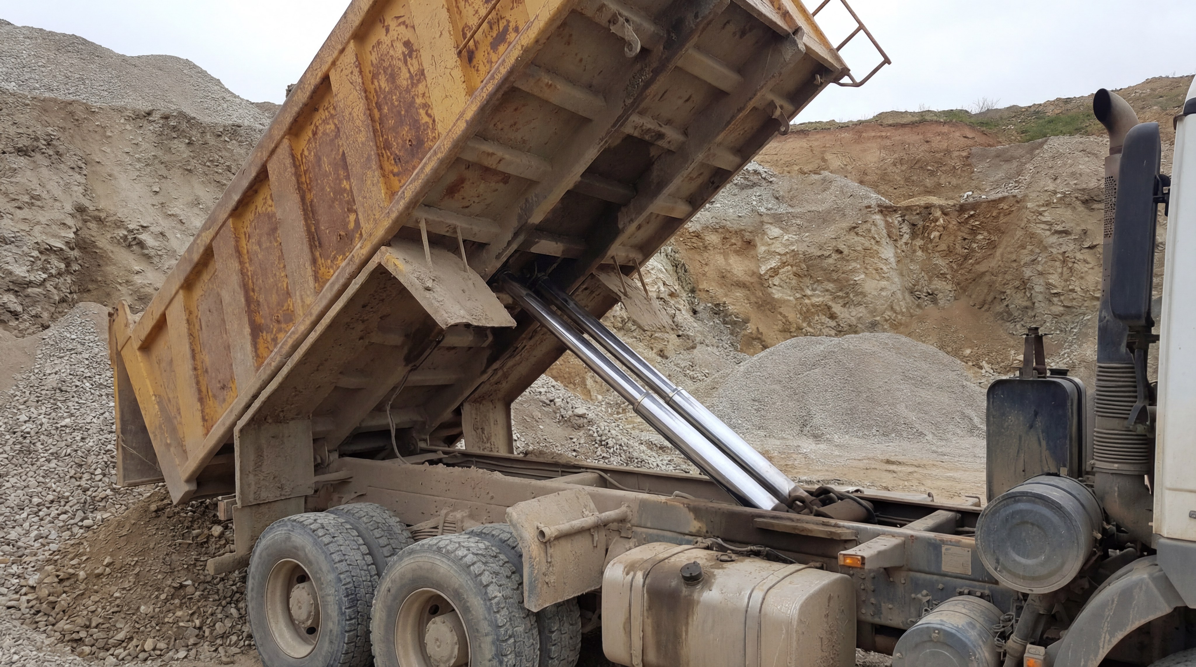
Gravity acts as the primary “motor” for retraction by pulling the load downward, which pushes the piston back and forces the hydraulic oil out of the cylinder. In applications like dump trucks or lift tables, the weight of the equipment is all that is needed to reset the system.
Relying on gravity is a fundamental aspect of how a one way hydraulic cylinder functions without a second hydraulic line. When you open the return valve, the load’s potential energy is converted into fluid motion, clearing the chamber for the next cycle.
Controlled Descent via Gravity
To prevent a heavy load from crashing down, you must use a flow control valve to restrict the oil as it exits the cylinder. This allows you to achieve a smooth, controlled descent that protects both your machinery and your personnel.
Wait, there’s more.
- Retraction requires zero electrical or pump power.
- System resets automatically under its own weight.
- Simplified valves prevent “hunting” during descent.
- Cooling occurs as oil rests in the reservoir.
External Load Requirements
For gravity retraction to work, your load must be heavy enough to overcome the internal friction of the cylinder’s seals and the backpressure of the return line. If the load is too light, the piston may stay extended or move back too slowly for your cycle requirements.
| Factor | Effect on Retraction | Solution | |
|---|---|---|---|
| Load Weight | Provides downward force | Ensure minimum load limit | |
| Seal Friction | Resists piston movement | Use low-friction seals | |
| Hose Diameter | Limits return oil speed | Use appropriately sized lines |
Utilizing gravity for retraction simplifies your hydraulic circuit and reduces the number of components that could potentially fail.
Designing your system around gravity return minimizes energy waste and leverages natural forces to maintain a high-cycle production environment.
Can Spring Return Mechanisms Improve Cycle Efficiency?
Spring return mechanisms improve efficiency by providing an automatic, mechanical force to retract the piston when gravity is insufficient or the cylinder is mounted horizontally. This internal spring is compressed during the extension stroke and releases its stored energy to pull the rod back the moment pressure is vented.
When you look at how a one way hydraulic cylinder operates in automated clamping or punching, the spring return is what allows for rapid, repetitive cycling. It ensures the tool is always ready for the next piece of material without requiring manual intervention.
Automatic Reset for Horizontal Tasks
In applications where the cylinder is not vertical, gravity cannot assist in pushing the oil back to the tank. The spring serves as a reliable “reset button,” ensuring the cylinder returns to its home position every time the valve is released.
Look at it this way.
- Enables mounting in any orientation (horizontal/inverted).
- Provides consistent return speed regardless of load.
- Simplifies automated logic for PLC-controlled machines.
- Reduces the risk of the piston getting “stuck” mid-stroke.
Balancing Force and Speed
While the spring is highly effective, you must account for the force it takes to compress it during extension. This “spring rate” subtracts a small amount from your total available lifting power, so you must size your cylinder accordingly.
| Spring Attribute | Benefit | Maintenance Requirement | |
|---|---|---|---|
| Spring Rate | Predictable return force | Check for fatigue over time | |
| Pre-load | Ensures full retraction | Verify seat alignment | |
| Enclosure | Protects from debris | Monitor for internal rust |
Integrating a spring return transforms a simple lifting tool into a high-speed industrial actuator capable of thousands of cycles per day.
Using a spring-return model allows you to maintain high productivity in complex assembly lines where gravity cannot be leveraged.
Where Are One Way Cylinders Used in Industrial Plants?
Industrial plants utilize one way cylinders in equipment where high force is needed for a single task, such as stamping, clamping, or lifting heavy raw materials. Their robust nature makes them ideal for the high-vibration and dirty environments often found in manufacturing and mining.
The versatility of how a one way hydraulic cylinder works across different sectors makes it a staple of modern engineering. From the forklifts in your warehouse to the massive presses on your factory floor, these cylinders provide reliable power with minimal maintenance overhead.
Essential Industry Applications
In construction, you will find single-acting cylinders powering the outriggers that stabilize cranes on uneven ground. In the logistics sector, they are the primary force behind the masts of pallet jacks and small freight elevators.
But that’s not the half of it.
- Manufacturing: Providing clamping force for CNC machining.
- Waste Management: Powering the ram in vertical trash compactors.
- Agriculture: Raising and lowering heavy implements on tractors.
- Aerospace: Controlling the deployment of landing gear and flaps.
Reliability in Harsh Conditions
Because these cylinders have a simplified internal design, they are far more resistant to the ingress of dust and moisture than their more complex counterparts. This makes them the first choice for outdoor equipment that must operate in rain, mud, or extreme heat.
| Industry | Primary Use Case | Performance Requirement | |
|---|---|---|---|
| Mining | Ore Crushing Jacks | Extreme shock resistance | |
| Logistics | Dock Levelers | High cycle reliability | |
| Construction | Concrete Pump Rams | Dirt and slurry tolerance |
The widespread adoption of this cylinder type is a testament to its efficiency and the ease with which it integrates into diverse hydraulic systems.
These actuators prove that simplicity in engineering often leads to the highest levels of field reliability and long-term performance.
How Do You Calculate Force Requirements for Your Load?
To calculate force requirements, you must multiply the operating pressure of your system by the surface area of the cylinder’s piston. This fundamental math is the starting point for how to specify force & stroke—start with “how does a hydraulic cylinder work” to ensure your machinery isn’t underpowered.
Understanding the relationship between PSI and bore size is critical to how a one way hydraulic cylinder works in your specific setup. If your calculation is off by even a small margin, your equipment may fail to lift its intended load, causing safety risks and production delays.
The Force Calculation Formula
The standard formula (Force = Pressure × Area) assumes a 100% efficient system, but you should always include a safety factor. In the real world, seal friction and internal backpressure will reduce the effective output by about 10% to 15%.
Consider this logic.
- Measure the internal bore diameter (not the outside).
- Calculate the area using the formula (π × radius²).
- Multiply the result by your pump’s maximum PSI.
- Subtract any internal spring resistance if applicable.
Precision Load Mapping
When specifying a cylinder, you must also consider the “column strength” of the rod to prevent buckling under heavy loads. A cylinder with a long stroke and a thin rod may bend if you apply too much force, even if the hydraulic pressure is within limits.
| Metric | Measurement Unit | Strategic Importance | |
|---|---|---|---|
| Bore Size | Inches (in) | Primary power multiplier | |
| System PSI | lbs per sq inch | Total energy input | |
| Rod Diameter | Inches (in) | Structural rigidity |
Accurate force mapping allows you to select a cylinder that operates comfortably within its limits, extending the life of your seals and pump.
Taking the time to perform these calculations correctly prevents the costly mistake of installing an undersized actuator that cannot handle your peak loads.
What Maintenance Prevents Premature Cylinder Failure?
Preventative maintenance involves regularly inspecting the rod for damage, checking fluid quality, and monitoring seal integrity to ensure your cylinder lasts for years.
Since you are dealing with a single-acting system, the breather port and the rod seal are your primary areas of concern. If dust or moisture enters through the breather, it will contaminate your oil and eventually scour the internal walls of the cylinder barrel.
Fluid Health and Filtration
The hydraulic oil is the lifeblood of how a one way hydraulic cylinder operates; contaminated oil acts like liquid sandpaper on your precision-ground parts. Regularly changing filters and performing oil analysis can catch microscopic metal shavings before they cause a total system failure.
Think about it.
- Contaminated oil causes 80% of hydraulic failures.
- Moisture leads to internal rust and pitting.
- High heat breaks down the chemical properties of oil.
- Air in the fluid causes “spongy” cylinder movement.
Rod and Seal Preservation
You should always keep the piston rod clean and lightly lubricated to prevent the “wiper” seal from wearing out prematurely. A scratched or pitted rod will tear through seals like a saw, leading to external oil leaks and a loss of system pressure.
| Maintenance Task | Frequency | Expected Outcome | |
|---|---|---|---|
| Visual Leak Check | Daily | Early detection of seal wear | |
| Rod Cleaning | Shift-change | Prevents debris ingress | |
| Pressure Testing | Quarterly | Identifies internal bypass |
By treating your hydraulic cylinders as precision instruments rather than simple iron bars, you significantly reduce your annual repair costs.
A proactive maintenance strategy ensures that your equipment remains an asset rather than a constant source of frustration and expense.
How Do Bore and Rod Sizes Affect System Performance?
Bore and rod dimensions directly dictate the lifting capacity, extension speed, and structural stability of how a one way hydraulic cylinder works. You must understand how to select bore and rod sizes using a hydraulic cylinder cross section to optimize your machine for both power and efficiency.
A larger bore allows you to lift heavier loads at the same pressure, but it also requires more oil volume to move, which can slow down your cycle times. Conversely, a thicker rod provides the strength needed for long-stroke applications but reduces the amount of space available for hydraulic oil.
The Power vs. Speed Trade-off
When you increase the bore diameter, the surface area increases exponentially (πr²), giving you much more tonnage for every pound of pressure. However, your pump must work longer to fill that larger space, meaning you must choose between brute force and rapid movement.
It’s a strategic choice.
- Large bore = High power, lower speed.
- Small bore = Lower power, higher speed.
- Thick rod = High buckling resistance.
- Standard rod = Lower weight and cost.
Sizing for Dynamic Stability
In applications where the cylinder extends several feet, the rod diameter becomes a critical safety factor. A rod that is too thin will “flex” or buckle under compression, causing the seals to wear unevenly and potentially leading to a catastrophic mechanical failure.
| Dimension | Increased Size Result | Decreased Size Result | |
|---|---|---|---|
| Bore Size | Massive lifting force | Faster cycle times | |
| Rod Size | Better side-load support | Reduced material cost | |
| Port Size | Faster fluid transfer | Throttled movement speed |
Choosing the correct dimensions involves balancing the physical constraints of your machine with the performance requirements of your specific application.
Precision sizing is the secret to a hydraulic system that feels “right”—delivering exactly the power and speed you need without wasting energy.
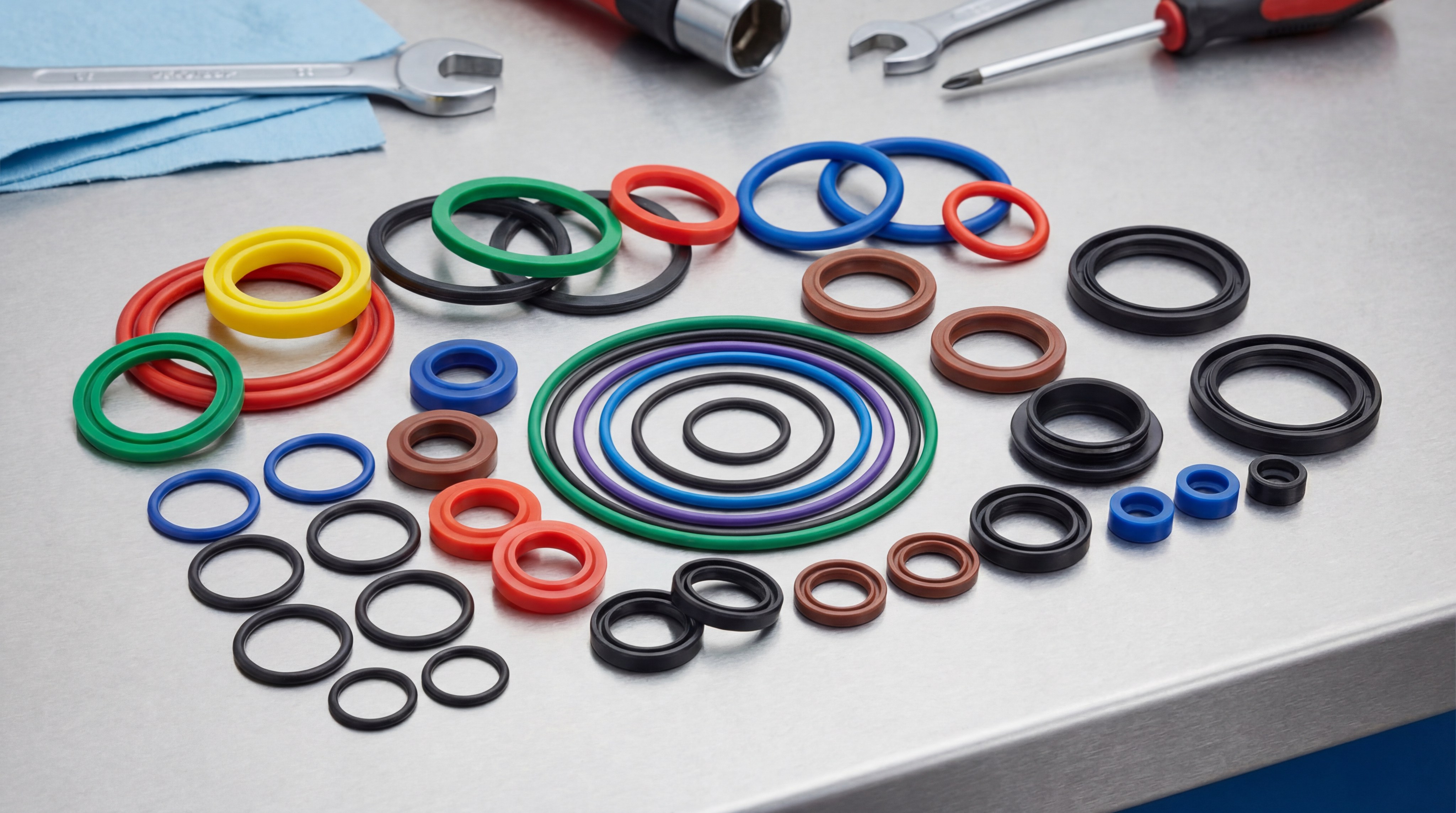
Why Is Seal Quality Critical for One Way Operation?
Seal quality is the single most important factor in maintaining the pressure integrity and operational lifespan of how a one way hydraulic cylinder works. In a single acting hydraulic cylinder , the rod seal is constantly exposed to the external environment, making it the first line of defense against contamination.
Investing in premium seals made from materials like Polyurethane or Viton ensures that your system remains leak-free even under extreme temperature swings. A cheap seal might save you ten dollars today, but it can cost you thousands in lost oil and environmental cleanup fees tomorrow.
Preventing Environmental Ingress
The “wiper” seal on the outside of the cylinder head is designed to scrape off dust, mud, and ice before the rod retracts into the barrel. If this seal fails, abrasive particles will enter the hydraulic chamber, destroying the polished internal surfaces of your equipment.
It’s about protection.
- Rod seals hold the main system pressure.
- Wiper seals exclude external contaminants.
- Wear bands prevent metal-to-metal contact.
- Static seals prevent leaks at end-caps.
Material Compatibility
You must match your seal material to the type of hydraulic fluid you are using and the ambient temperature of your workspace. Using standard Nitrile seals in a high-heat environment or with fire-resistant fluids will cause them to swell and fail within weeks.
| Seal Material | Temperature Range | Best Environment | |
|---|---|---|---|
| Nitrile (NBR) | -30°C to 100°C | Standard indoor plants | |
| Viton (FKM) | -20°C to 200°C | High-heat foundries | |
| Polyurethane | -40°C to 80°C | Heavy construction sites |
Selecting the optimal one way hydraulic cylinder is a strategic decision that directly influences the longevity and profitability of your operations. By focusing on high-grade components and precise engineering specifications, you ensure your machinery delivers consistent performance in any environment. Our mission is to provide you with the most durable, high-efficiency hydraulic solutions tailored to your unique industrial requirements.
To discuss your specific technical needs and receive a professional consultation, contact us today and let our engineering team help you optimize your hydraulic systems.
Frequently Asked Questions
Can I use a one way cylinder for pulling loads?
Typically no, as standard single-acting cylinders are designed for pushing. Pulling requires a double-acting design or a specialized “pull-type” single-acting configuration where the port is located at the rod end.
What’s the best way to prevent cylinder rust?
The most effective method is to store the cylinder with the rod fully retracted, keeping the precision-ground steel submerged in protective hydraulic oil rather than exposed to humid air.
Can I mount a gravity-return cylinder horizontally?
No, a gravity-return model will fail to retract in a horizontal position because there is no weight to push the oil back. For horizontal applications, you must use a spring-return model.
What’s the best fluid for high-temperature applications?
For high-heat environments like foundries, you should use fire-resistant hydraulic fluids combined with specialized Viton (FKM) seals that can withstand temperatures exceeding 200°C.
Can I convert a single-acting cylinder to double-acting?
This is generally not possible as the cylinder barrel must have a second port and the piston must have seals rated for pressure on both sides, which single-acting units lack.